
Segment core forming stator core of rotary electric machine and method for manufacturing the segment core

a technology of rotary electric machines and segment cores, which is applied in the direction of dynamo-electric machines, electrical apparatus, magnetic circuit shapes/forms/construction, etc., can solve the problems of deteriorating material yield in the manufacturing of segment cores, and achieve accurate and stably performed effects

Active Publication Date: 2014-03-25
DENSO CORP
View PDF5 Cites 0 Cited by
  • Summary
  • Abstract
  • Description
  • Claims
  • Application Information

AI Technical Summary

Benefits of technology

[0008]Taking the situation set forth above into consideration, the present disclosure provides segment cores of a stator core for a rotary electric machine, which are able to enhance material yield in manufacturing the segment cores, and also provides a method of manufacturing the segment cores.
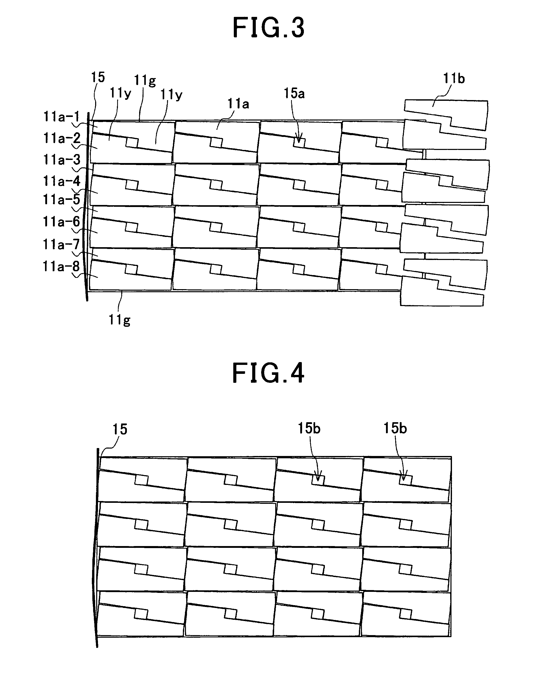
[0011]Thus, the spaces of slot-predetermined portions in the respective L-shaped right-angle portions of the combined segment outlines are mutually utilized in arranging the two segment outlines. Accordingly, the excess regions outside the segment outlines are efficiently reduced. Thus, according to the present disclosure, the excess regions, or wastes, remained after cutting out segment core members from the steel sheet member are drastically reduced to thereby enhance material yield in manufacturing the segment cores.
[0015]Thus, the spaces of slot-predetermined portions in the respective L-shaped right-angle portions of the combined segment outlines are mutually utilized in arranging the two segment outlines. Accordingly, the excess regions outside the segment outlines are effectively reduced. Thus, according to the present disclosure, the excess regions, or wastes, remained after cutting out segment core members from the steel sheet member are drastically reduced to thereby enhance material yield in manufacturing the segment cores.
[0017]According to the present disclosure, space efficiency in the array is enhanced, and thus material yield in manufacturing the segment cores is more favorably enhanced.
[0021]According to the present disclosure, the pilot holes are provided by effectively utilizing the excess regions each having at least three directions confronting the segment outlines. Further, owing to the provision of the pilot holes, the punching process for the steel sheet member is accurately and stably performed.

Problems solved by technology

Such large excess regions have raised a problem of deteriorating material yield in manufacturing segment cores.

Method used


Image

  • Segment core forming stator core of rotary electric machine and method for manufacturing the segment core
  • Segment core forming stator core of rotary electric machine and method for manufacturing the segment core
  • Segment core forming stator core of rotary electric machine and method for manufacturing the segment core

Examples


modification 1

[0058](Modification 1)

[0059]FIG. 5 is a plan view illustrating the steel sheet member 15 after segment core members have been cut out, according to Modification 1. The steel sheet member 15 of the first embodiment has not particularly been provided with pilot holes for the conveyance or positioning of the steel sheet member 15. In this regard, as shown in FIG. 5, the steel sheet member 15 of Modification 1 is provided with pilot holes 16 effectively utilizing the portions as the excess regions (waste 15b) in the steel sheet member 15 of the first embodiment. As shown in FIG. 5, the pilot holes 16 are formed in the excess regions each having four directions confronting the segment outlines 11a. Specifically, one pilot hole 16 is formed in each of the minimum units which are located along either longitudinal edge of the steel sheet member 15.

[0060]In Modification 1, owing to the provision of the pilot holes 16, the punching process of the steel sheet member 15 is accurately and stably...

modification 2

[0061](Modification 2)

[0062]FIG. 6 is a plan view illustrating the steel sheet member 15 after segment core members have been cut out, according to Modification 2. In the embodiment described above, the two segment outlines 11a forming a minimum unit have been arranged such that a face-to-face relationship is established between the inner long edges (11e, 11e) and between the inner short edges (11f, 11f). In this regard, as shown in FIG. 6, the two segment outlines 11a configuring the minimum unit in Modification 2 are arranged so that only the inner long edges (11e, 11e) are opposed to each other. Also, in Modification 2, five minimum units are arranged in the widthwise direction of the steel sheet member 15.

[0063]In Modification 2, the excess regions (wastes 15b) in the steel sheet member 15 are more drastically reduced. Thus, material yield in manufacturing the segment cores is more favorably enhanced.

modification 3

[0064](Modification 3)

[0065]FIG. 7 is a plan view illustrating the steel sheet member 15 after segment core members have been cut out, according to Modification 3. In Modification 3, the length of the confrontation between the inner long edges (11e, 11e) of the two segment outlines 11a configuring the minimum unit is shortened compared to Modification 2. Specifically, the two segment outlines 11a of the minimum unit are arranged being spaced apart from each other, or being offset from each other, in the longitudinal direction of the steel sheet member 15 to shorten the length of the confrontation.

[0066]Then, pilot holes 16A are provided in the excess regions (wastes 15b) formed by the offset arrangement of the two segment outlines 11a configuring each minimum unit. In this case, the pilot hole 16A is formed in each excess region that has at least three directions confronting the segment outlines 11a. For five minimum units arranged in the widthwise direction of the steel sheet membe...


PUM

PropertyMeasurementUnit
shapeaaaaaaaaaa
distanceaaaaaaaaaa
total areaaaaaaaaaaa

Abstract

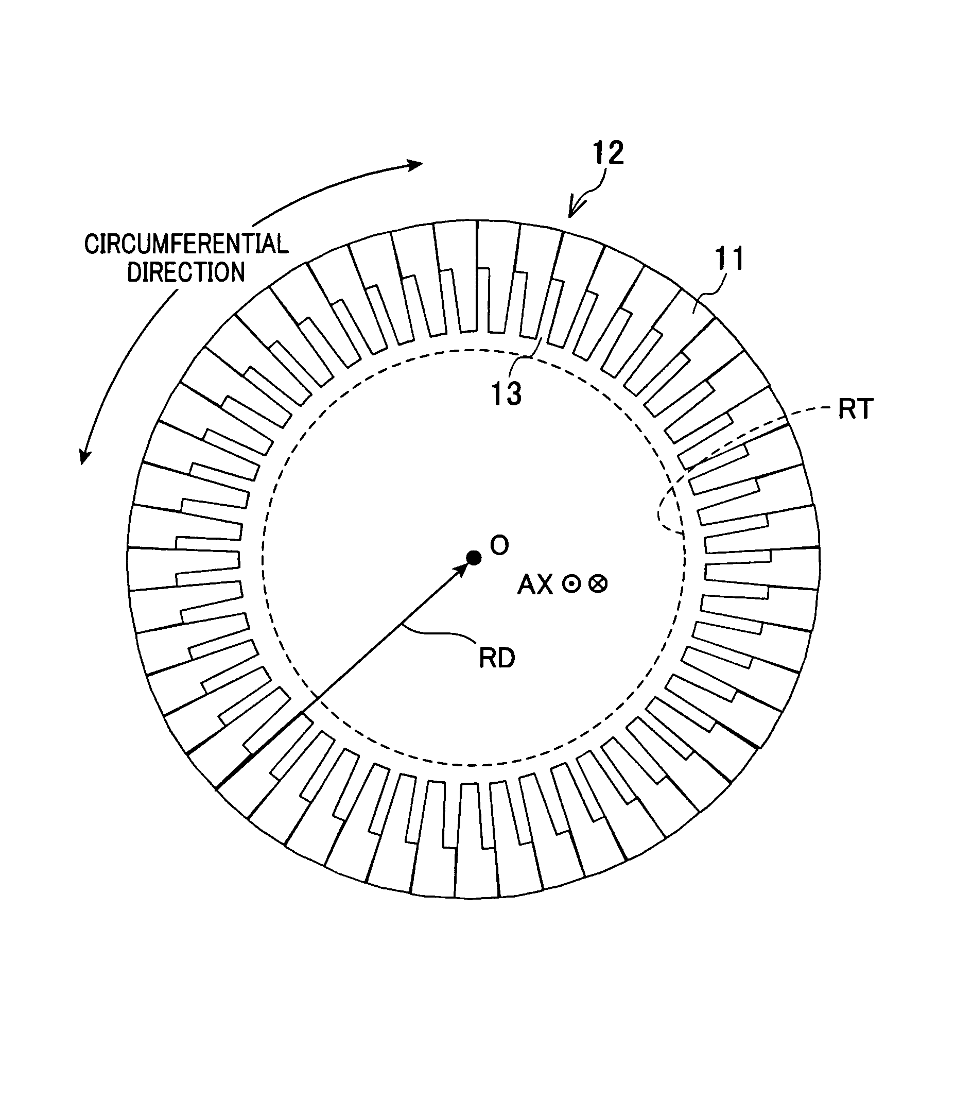
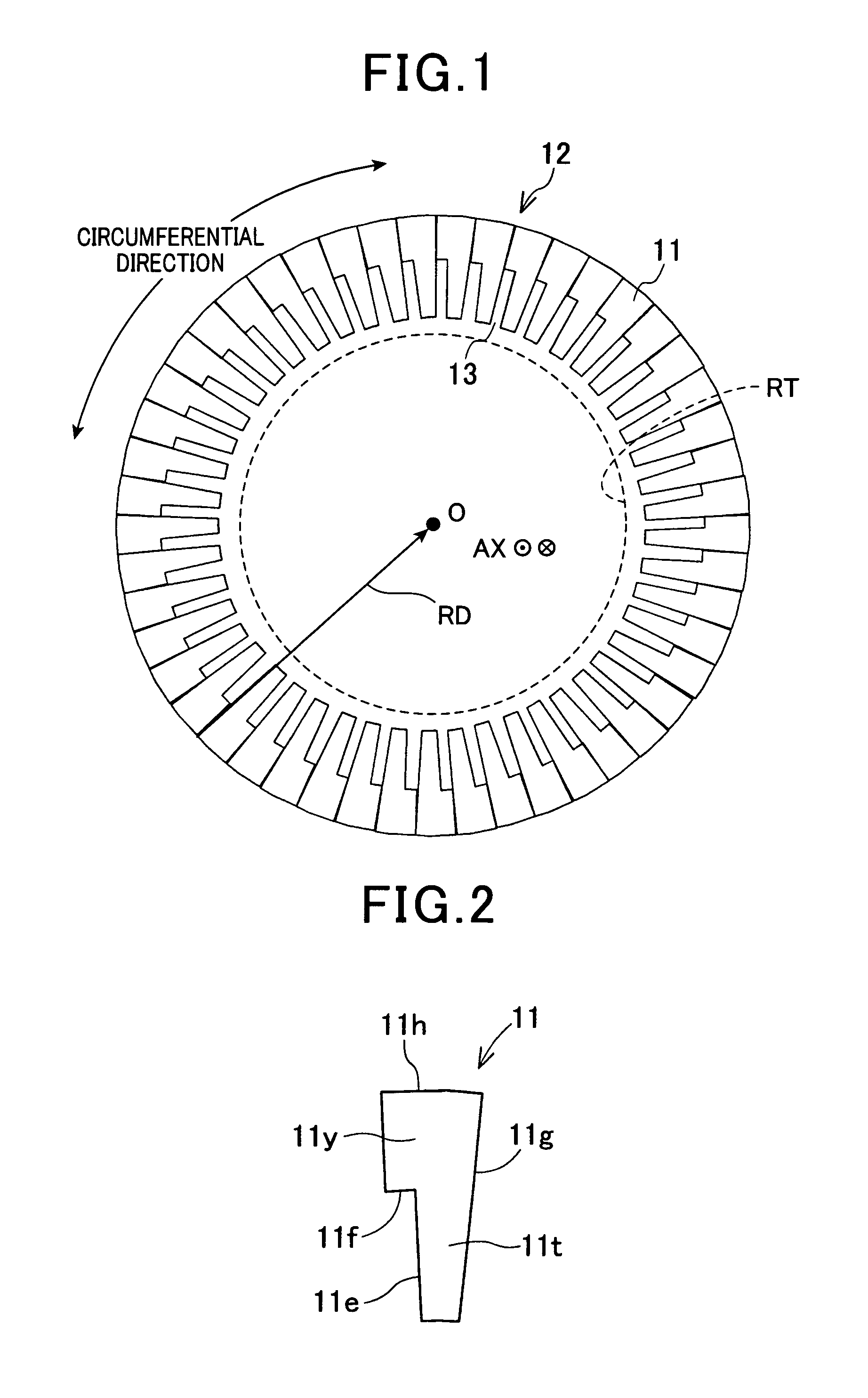
A segment core forms an annular-shaped stator core of a rotary electric machine. The stator core is formed into an annular shape by circumferentially connecting a plurality of segment cores, each segment core having a L shape and includes a yoke portion that forms the outer periphery of the stator core, a tooth portion that extends from the yoke portion to the rotary axis in a radial direction of the stator core, and a steel plate where the yoke portion and the tooth portion are formed wherein one edge of the segment core linearly extends along the yoke portion and the tooth portion in the radial direction of the stator core, the other edge forms a projection in the yoke portion jutting out from the tooth portion in the circumferential direction whereby a segment core is formed into a shape of an L.

Description

CROSS-REFERENCE TO RELATED APPLICATION[0001]This application is based on and claims the benefit of priorities from earlier Japanese Patent Application Nos. 2010-090394 and 2011-061077 filed Apr. 9, 2010 and Mar. 18, 2011, respectively, the descriptions of which are incorporated herein by reference.BACKGROUND[0002]1. Technical Field[0003]The present disclosure relates to sector-shaped segment cores configuring a stator core for a rotary electric machine, and a method for manufacturing the segment cores, and more specifically, to sector-shaped segment cores configuring a stator core for a rotary electric machine which is applied to a motor, a generator or the like installed such as in an electric vehicle and a hybrid vehicle, and to a method for manufacturing the segment cores.[0004]2. Related Art[0005]Segment cores configuring a stator core for a rotary electric machine are known. FIG. 9 shows such segment cores 1 configuring a stator core. The segment cores 1 are arranged on the sid...

Claims


Application Information

Patent Timeline
Patent Type & Authority Patents(United States)
IPC IPC(8): H02K3/46H02K1/16
CPCH02K1/16H02K15/024Y10T29/49009
Inventor UTAKA, RYOSUKE
Owner DENSO CORP
Learn More