Communication using modulated waves applied to an optical fiber

a technology of modulated waves and optical fibers, applied in the field of communication using modulated waves applied to optical fibers, can solve the problems of large power consumption, relatively short operational range of communication systems relying on such signals, and inability to meet the needs of underwater vehicles, etc., and achieve high data rate, high data rate, and long-distance wireless communication.

Active Publication Date: 2014-03-25
THE BOEING CO
View PDF10 Cites 18 Cited by
  • Summary
  • Abstract
  • Description
  • Claims
  • Application Information

AI Technical Summary

Benefits of technology

[0006]The phase-sensitive OTDR device may be positioned a significant distance away from the underwater vehicle that applies the mechanical waves. For example, the phase-sensitive OTDR device may be 25 km or more from the site at which the mechanical waves are applied to the optical fiber. Because the mechanical waves may have to travel a relatively short distance between the underwater vehicle and the optical fiber, a high data rate may be used. Thus, long distance high data rate wireless communication from an underwater vehicle may be accomplished. The phase-sensitive OTDR device may be coupled to a transmitter above sea. The transmitter may transmit information encoded in the mechanical waves received by the phase-sensitive OTDR device via the reflected light to a remote station such as a surface vessel or other system associated with the underwater vehicle. Accordingly, high data rate long distance wireless communication may be accomplished.

Problems solved by technology

Communication with underwater vehicles presents challenges due to attenuation properties of water.
Because some types of signals tend to attenuate significantly in water, communication systems that rely on such signals may have relatively short operational ranges, relatively low bandwidth capacity, or require large power.
For example, sonar and other sound-based communication techniques may suffer from relatively low bandwidth capacity.
The communication medium may reduce signal attenuation; however, the tether may limit range and mobility of the underwater vehicle.

Method used


Image

  • Communication using modulated waves applied to an optical fiber
  • Communication using modulated waves applied to an optical fiber
  • Communication using modulated waves applied to an optical fiber

Examples


Embodiment Construction

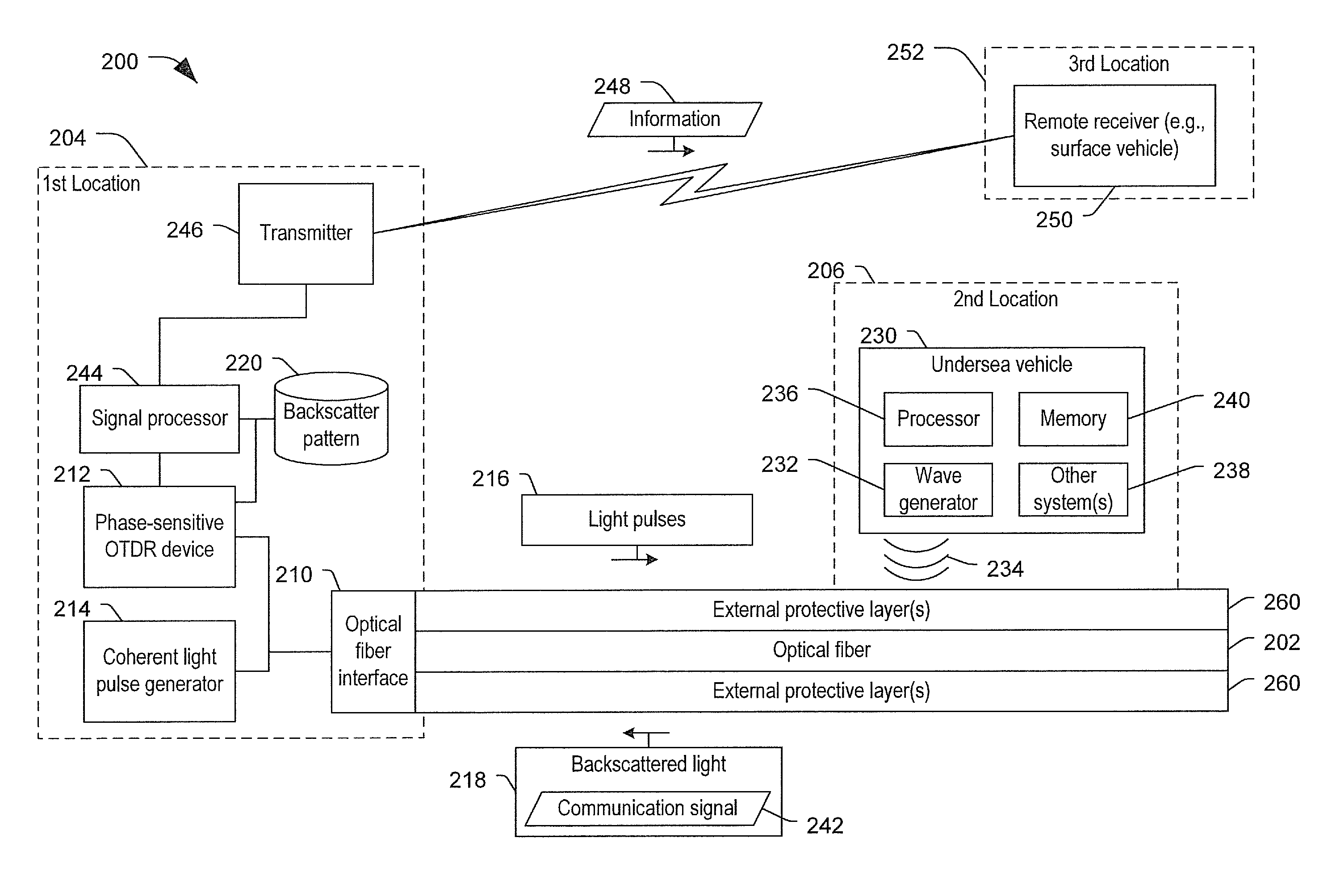
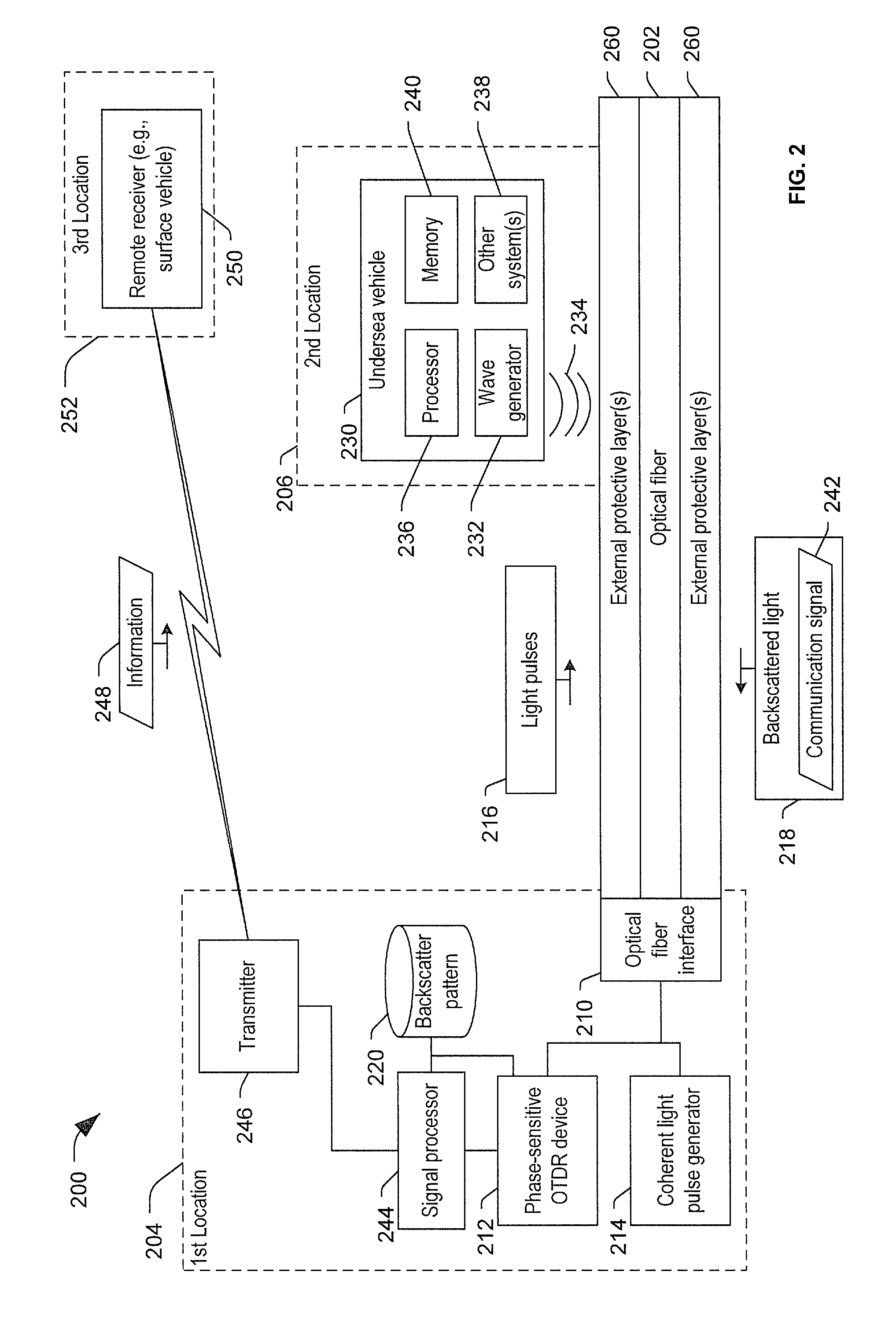
[0016]According to an illustrative embodiment, communication systems and methods that are capable of high-bandwidth, long-range communications are disclosed. The communication systems may utilize modulated waves (e.g., mechanical waves) to transfer a detectable signal to an optical fiber, enabling high-bandwidth, long distance wireless communication between an underwater vehicle and multiple locations.

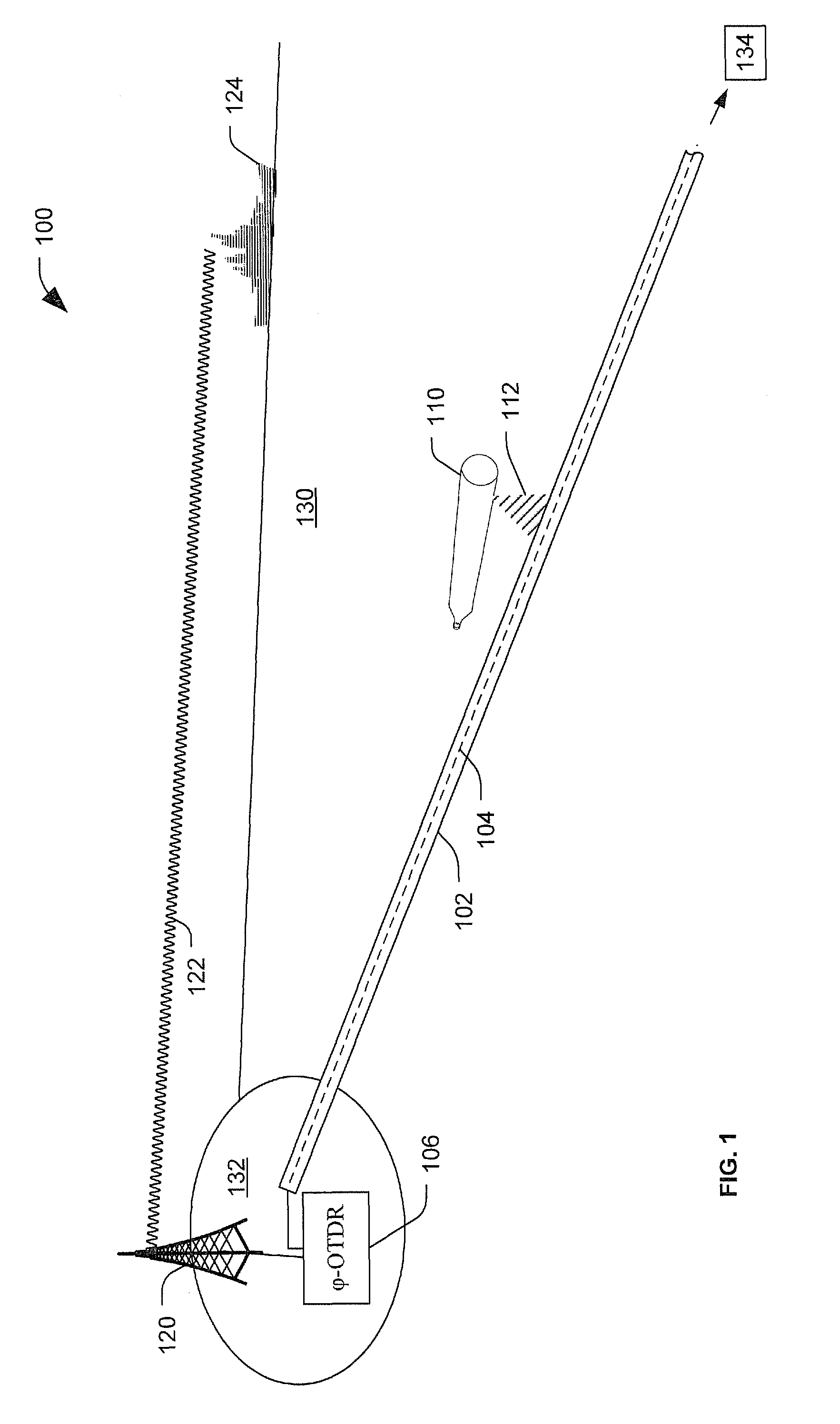
[0017]FIG. 1 illustrates a wireless communication system 100. The wireless communication system 100 includes an optical fiber 102 that is adapted to carry light pulses 104. A phase-sensitive optical time domain reflectometry (OTDR) device 106 may be coupled to the optical fiber 102. The phase-sensitive OTDR device 106 may be adapted to receive reflections of the light pulses 104. The wireless communication system 100 also includes an underwater vehicle 110. The underwater vehicle 110 may be adapted to apply mechanical waves 112 to the optical fiber 102. The mechanical waves 112 may cau...


PUM


Abstract

A particular method includes applying light pulses to an optical fiber and receiving backscattered light at a phase-sensitive optical time domain reflectometry (OTDR) device. The backscattered light includes portions of the applied light pulses that are backscattered by the optical fiber. The method also includes determining a difference between the backscattered light and a backscatter pattern associated with the optical fiber. The method also includes determining a communication signal encoded in the backscattered light based on the difference, where the communication signal is encoded in the backscattered light responsive to mechanical waves applied to the optical fiber at a location remote from the phase-sensitive OTDR device.

Description

FIELD OF THE DISCLOSURE[0001]The present disclosure is generally related to communication using modulated waves applied to an optical fiber.BACKGROUND[0002]Communication with underwater vehicles presents challenges due to attenuation properties of water. Because some types of signals tend to attenuate significantly in water, communication systems that rely on such signals may have relatively short operational ranges, relatively low bandwidth capacity, or require large power. For example, sonar and other sound-based communication techniques may suffer from relatively low bandwidth capacity.[0003]To avoid issues with signal attenuation in free-space (e.g., using water as a communication medium) a tether that includes a communication medium such as wires or optical fiber may be used. The tether may connect an underwater vehicle to a receiving system. The communication medium may reduce signal attenuation; however, the tether may limit range and mobility of the underwater vehicle.SUMMAR...

Claims


Application Information

Patent Timeline
Patent Type & Authority Patents(United States)
IPC IPC(8): H04B10/00H04B13/02H04B17/00
CPCH04B17/00H04B10/00H04B11/00H04B13/02H04B10/071
Inventor HILLER, NATHAN, D.
Owner THE BOEING CO
Why Eureka
Try Eureka