Aircraft landing gear

a landing gear and aircraft technology, applied in the direction of alighting gear, skis/runners, energy-saving operational measures, etc., can solve the problems of increasing the level of both atmospheric and noise pollution in the local vicinity of airports, the engine must be run at low power, and the fuel consumption is relatively high

Active Publication Date: 2014-04-01
AIRBUS OPERATIONS LTD
View PDF76 Cites 18 Cited by
  • Summary
  • Abstract
  • Description
  • Claims
  • Application Information

AI Technical Summary

Benefits of technology

[0014]The invention is advantageous in that it provides the potential for a mass optimised solution which has a low impact on the aircraft and landing gear baseline structure (i.e. an aircraft with a conventional landing gear without a driven wheel). The landing gear is changed little from a conventional landing gear, since the drive transmission is mounted externally. By using a drive pinion in meshing engagement with a toothed ring on the wheel, secure driving engagement is ensured without damage to the tyre on the wheel, and driving torque load paths are optimised. Given the very high acceleration experienced by the wheel during touch down, it is necessary to provide for disengagement of the drive transmission from the wheel using the actuator. There will be some deflection in the landing gear in response to grounds loads, and so it is important that the actuator can maintain the driving engagement during this movement.
[0018]The toothed ring and the drive pinion may have associated matching follower surfaces. The follower surfaces come together when the actuator presses the drive pinion into meshing engagement with the toothed ring, and act to control the orientation of the two gears relative to one another. This too helps to ensure that the driving engagement can be maintained.
[0019]The drive pinion may include a constant-velocity joint. This too helps to ensure that the driving engagement can be maintained.
[0020]The drive pinion and toothed ring may be in a sealed environment. This protects against contamination from environmental debris, which may affect the endurance life of the gears. For example, a brush type seal, or a flexible, possibly PTFE, type running seal may be used.
[0024]The drive transmission may include a toothed drive belt. This may be used to provide a lightweight, compact gearing solution.
[0025]The toothed ring preferably has a larger diameter than the drive pinion to develop a significant torque magnifying gear ratio. By making use of the large hub diameter in this way, a mass optimised solution can be achieved.

Problems solved by technology

As a result of the ground taxi speeds being relatively low the engines must be run at low power.
This means there is relatively high fuel consumption as a result of the poor propulsion efficiency at this low forward velocity.
This leads to an increased level of both atmospheric and noise pollution locally around airports.
Even when the engines are run at low power it is generally necessary to apply the wheel brakes to prevent excessive ground taxi speeds, which leads to a high degree of brake wear particularly as the brakes tend to be cold prior to take-off.
Since brakes are installed within the wheels of aircraft main landing gear, this region is very congested and so it is difficult to install drive motors on the wheel axle of main landing gear.
Therefore, development of these proposed systems has generally been limited to the nose landing gear.
Nose landing gear support low vertical load (approximately 5% of the aircraft weight) during ground taxi operations, which could lead to traction problems when the wheels are driven.
This is particularly the case when the aircraft centre of gravity is towards its aft limit and when the ground surface is slippery, e.g. when wet or icy.
An increase to the un-sprung mass of the landing gear is undesirable from a dynamic response perspective where this could result in high loads being induced into the landing gear and aircraft structure.
Furthermore the un-sprung landing gear components experience significantly higher vibration and acceleration loads than the sprung parts.
Furthermore, any drive system which is installed coaxial with the wheel axle cannot easily be removed.
This is generally not possible with an integrated drive system installed coaxial with the wheel axle.
Whilst this document addresses some of the short-comings of the prior art axle mounted wheel drive systems, the roller pressures on the tyre necessary to move the aircraft are considered to be so high as to lead to unacceptable damage to the tyre surface.
In addition, the shaft carrying the drum members is highly loaded in bending and therefore will need to be massive or it will suffer fatigue.
Therefore, this design is also unlikely to lead to a mass optimised solution, necessary for practical application.

Method used


Image

  • Aircraft landing gear
  • Aircraft landing gear
  • Aircraft landing gear

Examples


first embodiment

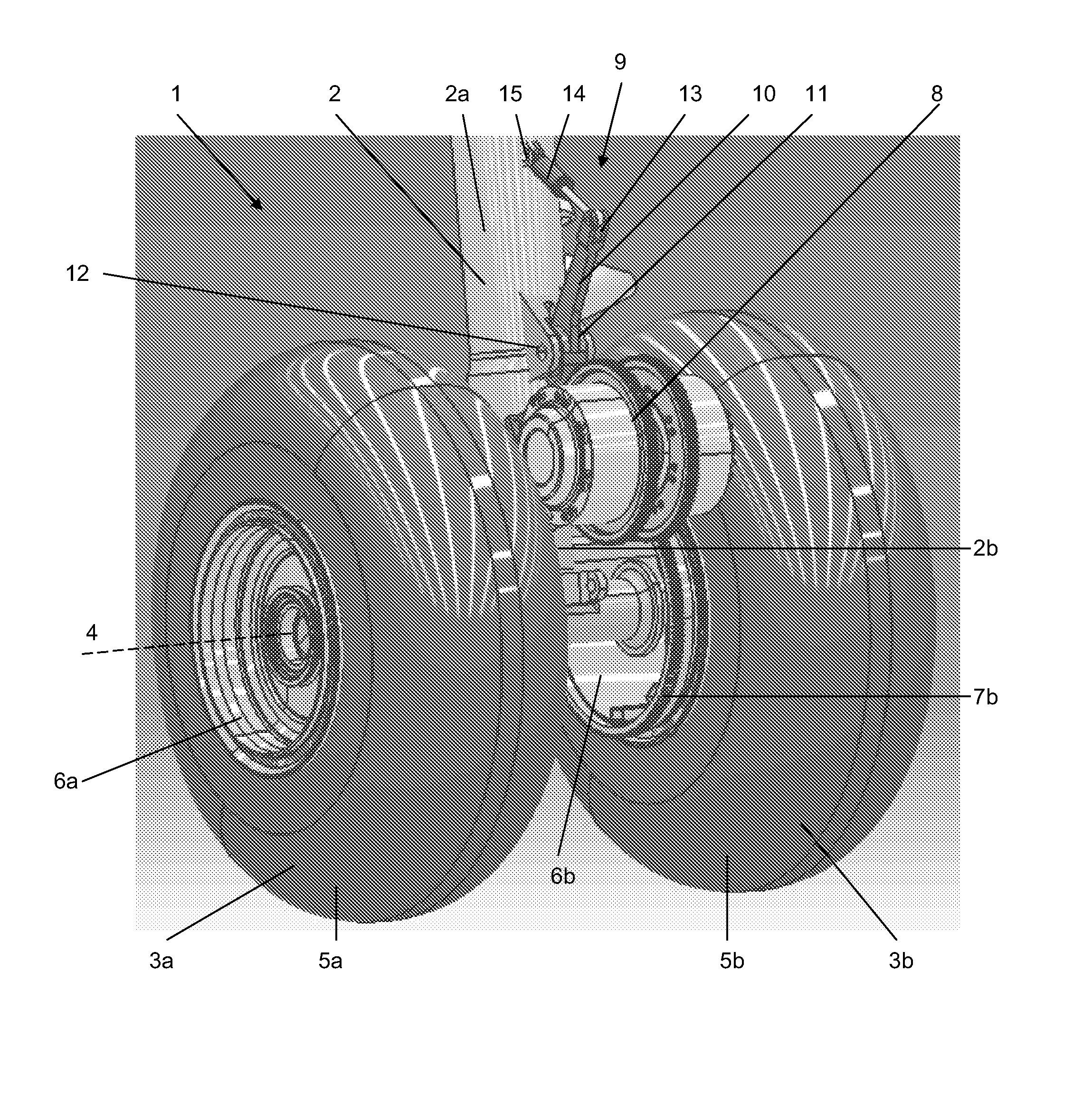
[0040]FIG. 1 illustrates a landing gear 1 in accordance with a The landing gear 1 includes a telescopic shock-absorbing main leg 2 including an upper telescopic part 2a (main fitting) and a lower telescopic part 2b (slider). The upper telescopic part 2a is attached to the remainder of an aircraft by its upper end (not shown). The lower telescopic part 2b supports an axle carrying a pair of wheels, one on either side of the main leg 2. The wheels 3a, 3b are mounted for rotation about a common wheel axis 4 with respect to the main leg 2. The upper part 2a is disposed above the shock-absorbing components inside the main leg and so will hereafter be referred to as the “sprung” part. The lower part 2b is disposed beneath the shock-absorbing components and so will hereafter be referred to as the “un-sprung” part, as is conventional.

[0041]Each wheel 3a, 3b includes a tyre 5a, 5b supported by a hub 6a, 6b. A toothed ring gear 7a, 7b is mounted to the outer diameter of each hub 6a, 6b (see ...

third embodiment

[0059]The drive transmission 60 includes electric motors 61 similar to the motors 41 of the These drive a twin stage geared arrangement 62 including planetary gears which output to the drive pinions 23. The drive transmission 60 provides a more compact arrangement compared to the drive transmission 50 but is heavier due to the twin stage geared arrangement 62.

sixth embodiment

[0060]In the embodiments described above, the drive transmission is mounted on the sprung part of a shock-absorbing main leg. FIG. 9 illustrates a landing gear 101 in accordance with a sixth embodiment, in which a drive transmission is mounted externally on the wheel axle. FIG. 9a) illustrates a rear view, FIG. 9b) illustrates a side view with the drive transmission engaged, and FIG. 9c) illustrates a side view with the drive transmission disengaged.

[0061]The landing gear 101 shares many features in common with the landing gear 1 described above and so only the differences between them will be described in the following.

[0062]The landing gear 101 includes a telescopic shock-absorbing main leg 102 including an upper telescopic part 102a (main fitting) and a lower telescopic part 102b (slider), with a torque link 102d between them. The lower telescopic part 102b supports an axle 102c carrying a pair of wheels 103, one on either side of the main leg 102 (note only wheel 103b is shown i...


PUM


Abstract

An aircraft landing gear comprising: a shock-absorbing main leg having a sprung part for attachment to an aircraft and an un-sprung part including a slider and an axle carrying at least one wheel, the wheel having a toothed ring gear; a drive transmission mounted externally on the sprung part, or on the un-sprung part, of the main leg, the drive transmission having at least one motor and a drive pinion for meshing with the toothed ring of the wheel; and an actuator for lifting the drive transmission into and out of driving engagement with the toothed ring and for maintaining the driving engagement as the landing gear deflects during a ground taxiing operation. Also, a method of operating the aircraft landing gear.

Description

RELATED APPLICATIONS[0001]The present application is National Phase of International Application Number PCT / EP2010 / 061343, filed Aug. 4, 2010, and claims priority from, British Application Number 0915009.5, filed Aug. 28, 2009 and British Application Number 1007562.0, filed May 6, 2010.FIELD OF THE INVENTION[0002]The present invention relates to an aircraft landing gear including a shock-absorbing main leg having a sprung part for attachment to an aircraft and an un-sprung part including a slider and an axle carrying at least one wheel. In particular, the invention relates to a drive for rotating the wheel whilst the aircraft is on the ground. The invention also relates to a method of operating the landing gear.BACKGROUND OF THE INVENTION[0003]Most aircraft ground taxi by using thrust produced by their main engine(s). As a result of the ground taxi speeds being relatively low the engines must be run at low power. This means there is relatively high fuel consumption as a result of th...

Claims


Application Information

Patent Timeline
Patent Type & Authority Patents(United States)
IPC IPC(8): B64C25/00
CPCB64C25/405Y02T50/823Y02T50/80B64C25/58
Inventor WILSON, FRASERBEDARRIDES, JEREMYPLATAGEA, VLADIMIR
Owner AIRBUS OPERATIONS LTD
Why Eureka
Try Eureka