Cartridge seal assemblies and associated methods

a technology of cartridge seals and components, applied in the direction of engine seals, mechanical equipment, engine components, etc., can solve the problems of decreasing the tensile and shear strength of soft seal materials, reducing the life of seals, and eventually wear of seals for static and dynamic applications, so as to achieve the effect of increasing the sealing for

Active Publication Date: 2014-04-01
BAL SEAL ENG LLC
View PDF22 Cites 20 Cited by
  • Summary
  • Abstract
  • Description
  • Claims
  • Application Information

AI Technical Summary

Benefits of technology

[0007]Another embodiment of the present cartridge seal assemblies comprises a cartridge defining a cavity, and a seal assembly disposed within the cavity. The seal assembly includes an annular sealing member having a lip configured for sealing engagement with the rotatable shaft. The seal assembly further includes a canted-coil spring disposed radially outward of the lip and a sealing retaining ring that is movable with respect to the canted-coil spring. The canted-coil spring applies a radially directed compressive force to the sealing member, forcing the lip against the rotatable shaft to apply a sealing force. Movement of the sealing retaining ring with respect to the canted-coil spring further compresses the spring, thereby increasing the sealing force.

Problems solved by technology

Seals for static and dynamic applications eventually wear out.
In dynamic applications, an increase in the area of contact between the seal and the sealing surface under high sealing stress results in a temperature increase, which causes a decrease in the tensile and shear strength of the softer seal material resulting in a decrease in seal life.
The greater the area of contact, the higher the temperature at the sealing area and the faster the seal will likely fail.
The higher hardness reduces flexibility, making it more difficult to affect sealing.
These materials thus generally make poor lip-type seals.
Since hard plastic materials that can withstand elevated temperatures generally have very low elongation, the range in tolerances of sealing stress under which they can function properly is limited.

Method used


Image

  • Cartridge seal assemblies and associated methods
  • Cartridge seal assemblies and associated methods
  • Cartridge seal assemblies and associated methods

Examples


Embodiment Construction

,” one will understand how the features of the present embodiments provide the advantages described herein.

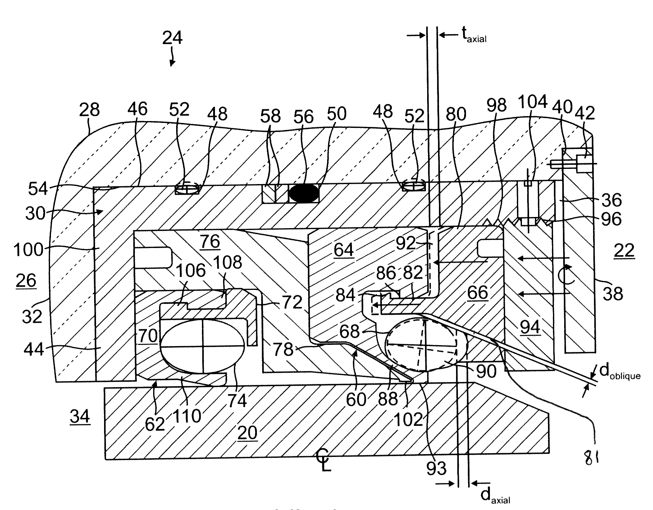
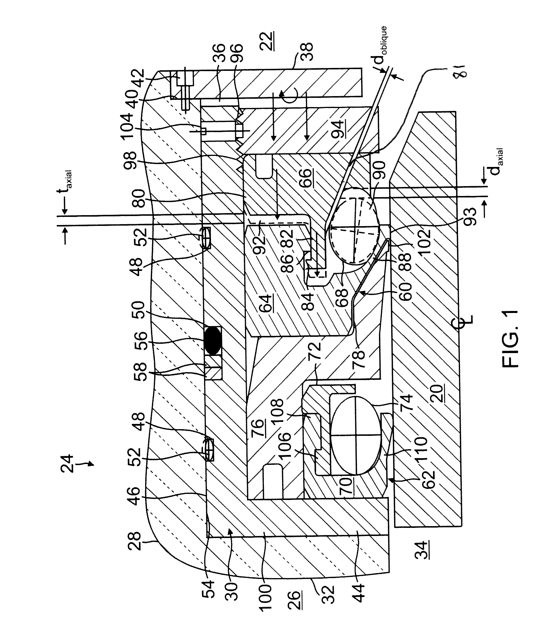
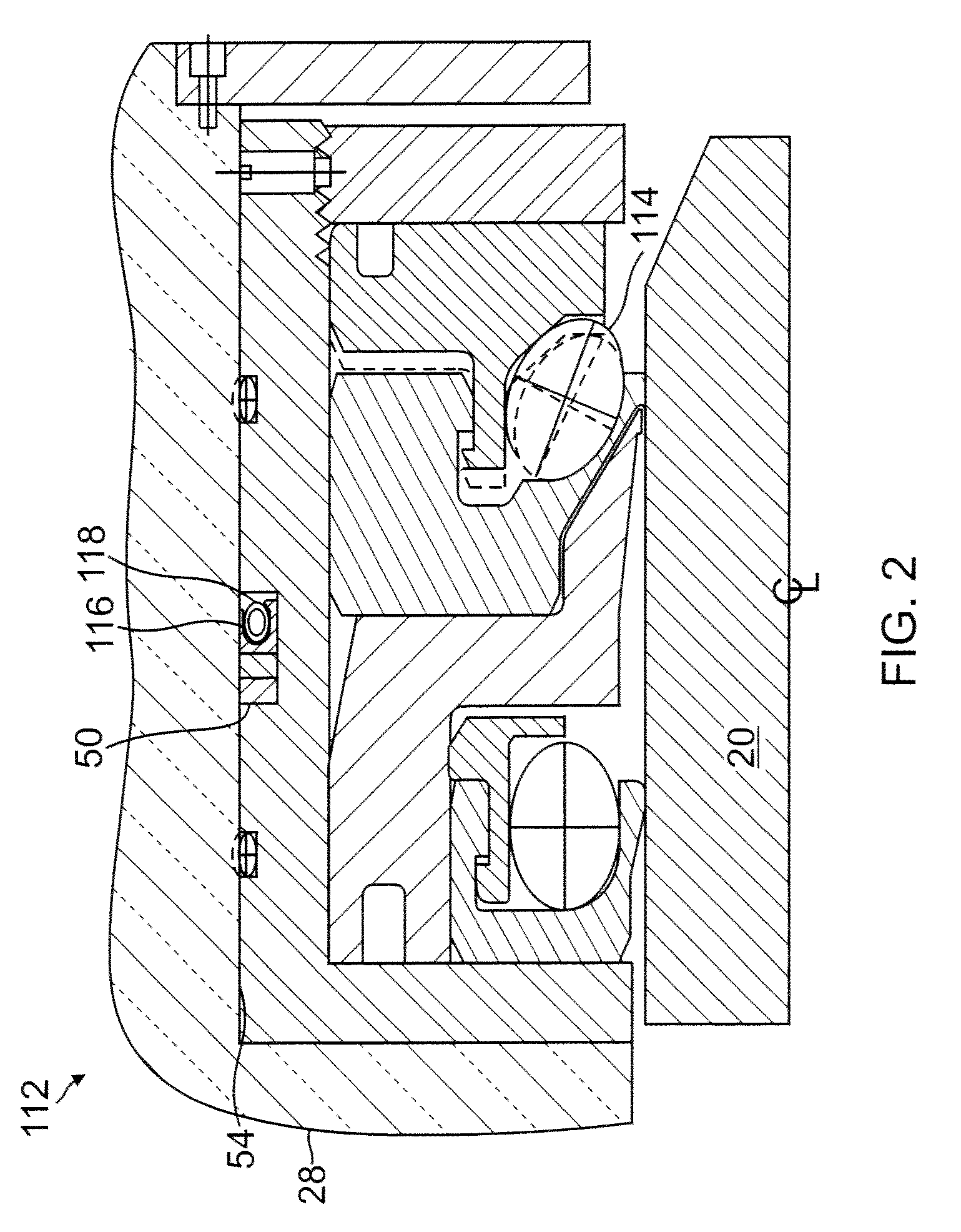
[0006]One embodiment of the present cartridge seal assemblies comprises a cartridge defining a cavity, and a seal assembly disposed within the cavity. The seal assembly includes an annular sealing member having a lip configured for sealing engagement with the rotatable shaft. The seal assembly further includes a sealing retaining ring and a canted-coil spring disposed between the sealing member and the sealing retaining ring. The sealing retaining ring is axially translatable toward and away from the sealing member. When the sealing retaining ring is translated axially toward the sealing member, the canted-coil spring is compressed between the sealing retaining ring and the lip of the sealing member with increased force, and the lip is forced radially against the shaft with increased force due to the increased compression in the spring.

[0007]Another embodiment of the present ca...


PUM


Abstract

The present cartridge seal assemblies pertain to rotary lip-type seals. In certain embodiments, a sealing member is constructed of a relatively hard material that increases the lifespan of the sealing member. The sealing member is energized with a canted-coil spring, which in some embodiments includes an adjustable spring force. The present embodiments enable control of sealing force to achieve an appropriate sealing force between the sealing member and the shaft based on factors such as temperature, pressure, rotary speed, properties of fluid media, etc. to achieve longer seal life.

Description

CROSS-REFERENCE TO RELATED APPLICATION[0001]This application claims priority to provisional application Ser. No. 61 / 233,398, filed on Aug. 12, 2009, the entire contents of which are hereby incorporated herein by reference.FIELD[0002]Cartridge seal assemblies are generally discussed herein with particular reference to seal assemblies having adjustable and non-adjustable force mechanisms.BACKGROUND[0003]Seals for static and dynamic applications eventually wear out. Accordingly, there is a need for a seal assembly that either lengthens the useful operating life before wear and / or that compensates for the wear to increase the useful operating life. Rotary lip-type seals are generally made from substantially soft materials such as elastomeric materials and certain types of soft plastic materials like polytetrafluoroethylene (PTFE). These materials adjust readily to variations in tolerances and in so doing vary the areas of contact between the seal and the sealing surfaces. In dynamic app...

Claims


Application Information

Patent Timeline
Patent Type & Authority Patents(United States)
IPC IPC(8): F16J15/34
CPCF16J15/322F16J15/3212F16J15/3232F16J15/3208
Inventor BALSELLS, PETEDILMAGHANIAN, FARSHIDCHANGSRIVONG, DEREK
Owner BAL SEAL ENG LLC
Why Eureka
Try Eureka