
Abutment inlay

a technology of inlay and overlay, which is applied in the field of inlay of dental components, can solve the problems of colouring, visible and unsightly exposure, and displacement of gingiva and the corresponding exposure of the implant structure, so as to improve the fit between inlay and overlay, and facilitate the manufacturing process of hybrid abutments.

Active Publication Date: 2014-04-01
STRAUMANN HLDG AG
View PDF12 Cites 2 Cited by
  • Summary
  • Abstract
  • Description
  • Claims
  • Application Information

AI Technical Summary

Benefits of technology

The purpose of this invention is to make it easier to make parts called hybrid abutments and other secondary components, and to improve how well the parts fit together.

Problems solved by technology

These materials have the necessary strength for withstanding the mechanical loads that occur, and they are at the same time sufficiently biocompatible for osseointegration and long term use in the mouth.
Although titanium and its alloys possess many qualities that make these materials particularly suited for dental implants, one large disadvantage is their colouring.
It is a relatively common occurrence that, after implant placement, some bone absorption (bone loss) occurs, which leads to a corresponding displacement of the gingiva and the exposure of the implant structure, including parts of the abutment.
The grey, metallic colour of titanium means that any such exposure is noticeable and unsightly.
In addition, when the abutment is made of metal the covering prosthesis must be opaque enough to prevent any metal colouring from showing through the prosthesis, as this will reduce the natural appearance of the restoration.
However, ceramic materials are also more brittle than metals, meaning these are harder to manufacture and consequently more expensive.
In addition the use of ceramic implants is still a developing field and the long term success of such implants is not yet known.
When the octagonal post portion is inserted into the octagonal cavity it is not possible to rotate the inlay relative to the overlay.
The creation of precisely connecting anti-rotation means, particularly within a brittle ceramic overlay, can be complex and lead to high manufacturing costs.

Method used


Image

  • Abutment inlay
  • Abutment inlay
  • Abutment inlay

Examples


Embodiment Construction

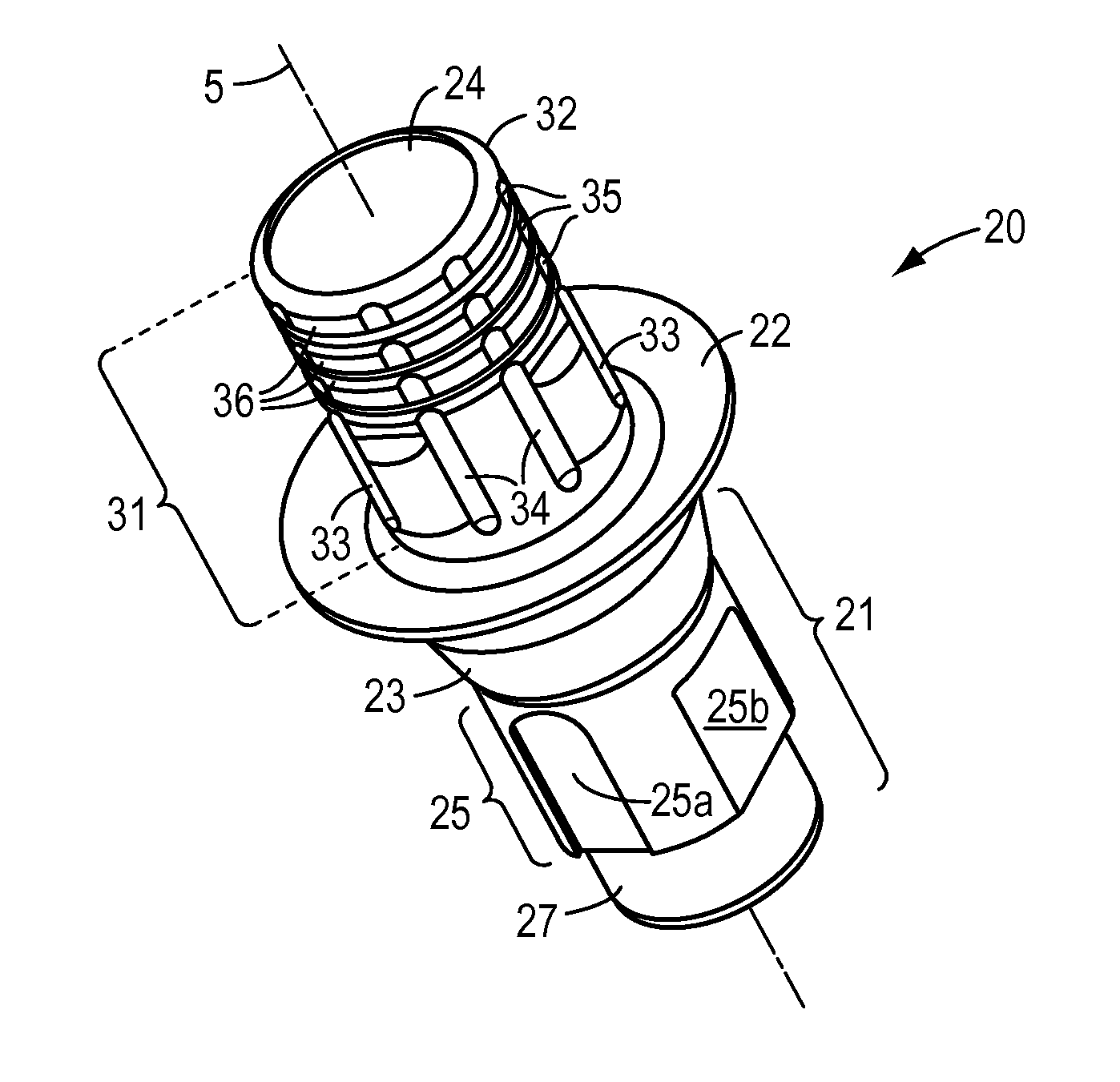
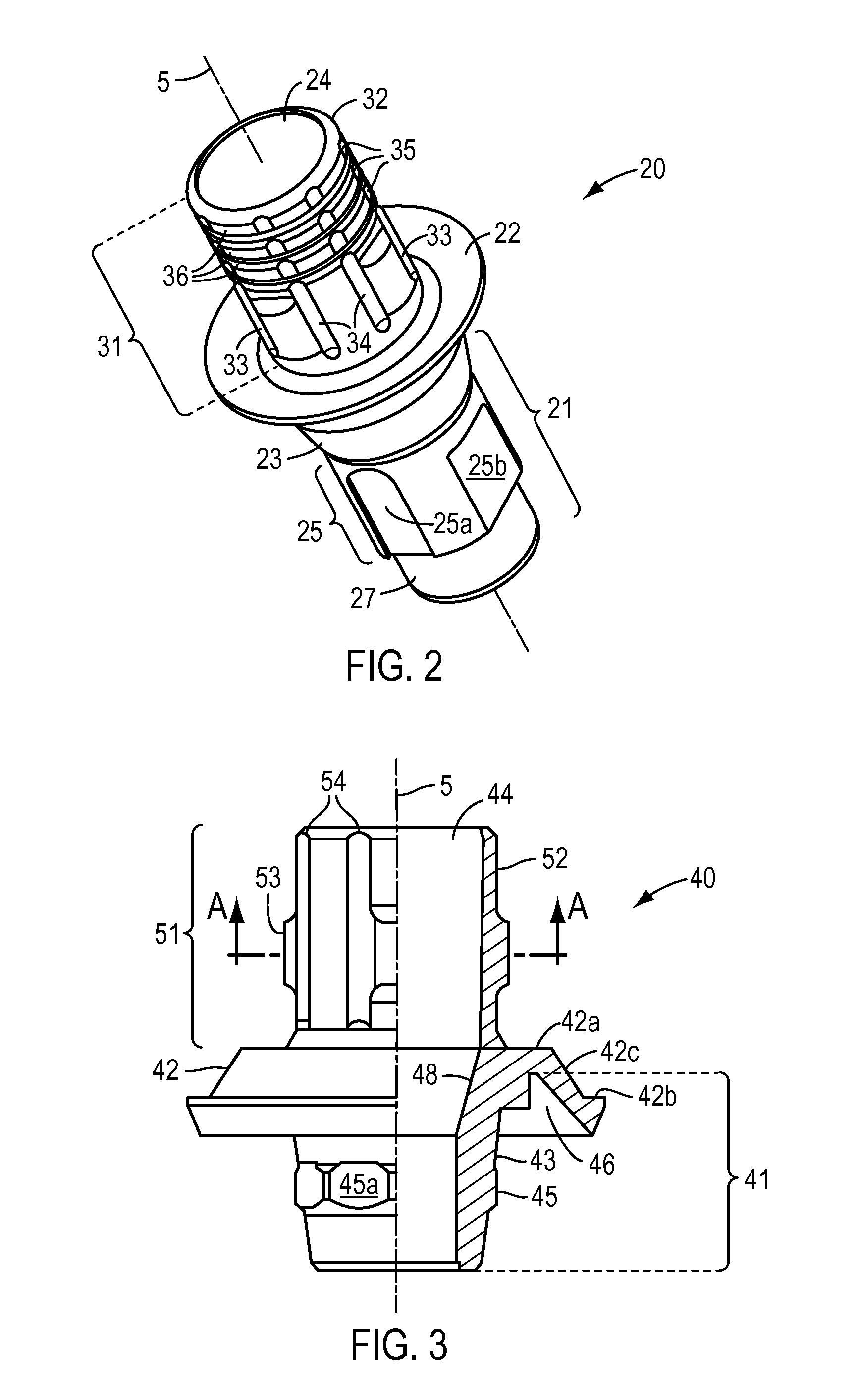
[0082]FIG. 2 shows an inlay 20 in accordance with the present invention. It comprises apical portion 21 having implant connection geometry. The apical portion 21 is shaped for insertion into an internal bore of a dental implant. Apical portion 21 comprises a conical portion 23 tapering in the apical direction and, apical of conical portion 23, anti-rotation means 25. In the present embodiment anti-rotation means 25 comprises a series of grooves 25a and flats 25b. These are positioned and dimensioned to co-operate with a number of protrusions within the bore of the implant, such that the inlay 20 is held in a rotationally locked position relative to the implant. Apical portion 21 further comprises, apical of the anti-rotation means 25, circular cylindrical guidance portion 27 which helps to centre the inlay 20 during insertion into the implant.

[0083]Coronal of the apical portion 21, the inlay 20 comprises a coronally facing platform 22 which acts as an abutment surface and axial stop...


PUM


Abstract

An inlay for connection to a dental implant, including implant connection geometry, for connecting the inlay to the implant and, coronal of the implant connection geometry, a post portion extending along a longitudinal axis, the post portion having a circular symmetric external surface and including at least one protrusion extending radially beyond said external surface, wherein the post portion further includes longitudinally extending grooves which extend radially inward of said external surface and are located directly adjacent to and on either side of the at least one protrusion such that the proximal end of said at least one protrusion is located radially inward of said external surface. The inlay is used in combination with an overlay including an accommodation cavity for housing the post portion of the inlay, the accommodation cavity having a circular symmetric cavity wall and at least one groove dimensioned such that the one or more protrusion of the inlay can be housed in the one or more groove of the overlay in order to inhibit relative rotation between the components.

Description

CROSS-REFERENCE TO RELATED APPLICATIONS[0001]This application claims priority to European Patent Application No. 11009618.7, filed Dec. 6, 2011, the disclosure of which is incorporated herein by reference in its entirety.BACKGROUND OF THE INVENTION[0002]This invention relates to an inlay of a dental component, in particular a dental abutment, for use in combination with a dental implant. The component consists of the inlay, which in use connects the component to the implant, and another part for carrying out the main function of the component, for example supporting a dental prosthesis. The two parts are in use fixed together and may be constructed of different materials.[0003]Dental implants are used to replace individual teeth or for anchoring more complex structures, which generally replace several or even all of the teeth. The materials used for dental implants are often titanium and alloys thereof. These materials have the necessary strength for withstanding the mechanical load...

Claims


Application Information

Patent Timeline
IPC IPC(8): A61C8/00
CPCA61C8/0059A61C8/0068A61C8/0066A61C8/0016A61C8/0054A61C8/005
Inventor VAN, OPHUYSEN, ANDREAS
Owner STRAUMANN HLDG AG
Learn More