Hypodermic drug delivery reservoir and apparatus

a technology of hypodermic drugs and reservoirs, applied in the direction of micro-needles, infusion needles, other medical devices, etc., to achieve the effects of improving the rupturing mechanism, preventing the fluid connection, and affecting the accuracy of the administered dos

Active Publication Date: 2014-04-01
AKTIVAX INC
View PDF133 Cites 46 Cited by
  • Summary
  • Abstract
  • Description
  • Claims
  • Application Information

AI Technical Summary

Benefits of technology

[0043]In FR-1.121.237 there is described a device for the hypodermic injection of liquids using a high pressurized liquid jet. The device comprises a compressible container for liquid medication which is attached to a unit having a fluid channel. The unit with the fluid channel is connected to a unit with a nozzle so that a continuous channel is being formed through which the liquid medication can be expelled. For a hypodermic injection the unit with the channel is placed on a mounting element so that the medication container is surrounded by a chamber and pressure is applied to said chamber by ignition of an explosive. The document FR-1.121.237 teaches that the medication container and the unit with the channel are combined by the user. The user fills the liquid to be injected into the medication container and tightly closes the medication container by screwing on the unit with the fluid channel. Such a process is not only cumbersome but it also bears the risk that the medication and / or the fluid channel is contaminated. The injection of a contaminated medical fluid is totally unacceptable in the therapeutic field. This problem of contamination is mostly unresolved in the prior art of hypodermic liquid injection. Furthermore the FR-1.121.237 does not give any information regarding the pressure of the liquid jet and how this pressure can be controlled to be in a specific range or how the pressure can be changed by the user to comply with his specific needs. A further drawback of the system described in FR-1.121.237 is that no means for purging air from the liquid chamber are described. However, air within the liquid chamber leads to disadvantageous effects as described further below.
[0044]Reference GB-697,643 describes a device for hypodermic injections using a flexible or collapsible element which is being compressed. The device described in this document is very complicated and uses a rechargeable pressure chamber into which a pressurized gas is introduced and in addition thereto a chamber with a hydraulic fluid is employed. With this device it is possible to control the pressure by which the liquid is being expelled from the container. However, a flexible container is needed into which the collapsible medication container is being introduced. From the function of this device it must be assumed that it is impossible to expel all of the fluid which is within the medication container. The document GB-697,643 further discloses a medication container which is sealed and can be used to store a medication under sterile conditions. However, this document does not disclose a medication container including a sterile nozzle. Therefore this document does not give an overall solution to the object of sterile injection.
[0045]U.S. Pat. Nos. 3,387,609, and 4,051,851 describe a prefilled disposable hypodermic syringe having a diaphragm, made from a resilient and penetrable material, at the dispensing end of a medicament vial, preventing the fluid connection between said medicament and the administration mean of the device. A rupturing member positioned in proximity to said diaphragm such that, upon presence of pressure in the vial said diaphragm collapse toward the rupturing member at which point the diaphragm is ruptured establishing a fluid communication between the vial and the administration means. Several other patents (referring to the above patents (including U.S. Pat. Nos. 4,0551,851; 4,072,149; 4,084,718; 6,354,603) repeat the fundamental idea of rupturing a sealed medicament reservoir in similar fashions and suffer from a common drawback, and incompetence with the device of the present invention. While U.S. Pat. Nos. 3,387,609 and 4,051,851 describes a rupturable reservoir one may understand that the rupturing is desired immediately upon performing the injection, and that excessive pressure built in the vial prior to the rupture of the diaphragm works against the purpose of the idea. Therefore the rupturing mechanism of the present invention is incompetence for controlling the drug administration pressure. It is also noted that the integrity of the prefilled package is not established and that the sealing of the medicament is limited.
[0046]The disadvantages listed above for the devices using collapsible reservoir are addressed by U.S. Pat. No. 6,258,063 which describes A hypodermic injection system allows for the generation of a high pressure liquid jet capable of passing through the skin. The system uses two regions, the first region being flexible or squeezable and the second region having at least one exiting orifice through which the liquid jet can be expelled. The flexible region can be deformed by a pressure change in the surrounding container generated by an activatable gas generator that generates pressure within the first region that causes the liquid to be expelled. The patent application describes two types of medication units—Type A and Type B—and types device construction to operate said medication units types. The Type B configuration comprises a medicament reservoir having flexible walls possibly Made from films or foils. The medicament is pressurized by exposing the reservoir wall to external pressure. Upon pressurizing the medicament a portion of the wall is displaced toward a rupturing member, thereupon the reservoir is ruptured and the medicament is expelled toward the administration means. U.S. Pat. No. 6,258,063 further describes means for controlling the pressure applied to the reservoir. Since this patent is limited pressurizing means which instantly deliver high pressure to the reservoir, provided by explosion, it does not refer to control mechanism that which prevent the rupture if the pressure in the reservoir has not reached a defined threshold. On the contrary, U.S. Pat. No. 6,258,063 refers to situation where it is needed to get rid of excess pressure due to the excessively high pressure that the explosion can generate. Thus the pressure control in U.S. Pat. No. 6,258,063 is limited to control of exhaust of the combustion products.
[0047]U.S. Pat. No. 6,258,063 also describes means of sealing the ruptured area around a fluid conduit such that the medicament is directed to the fluid conduit leading to the administration device. The sealing is achieved by venting the area around the ruptured portion which causes the walls around the ruptured area to press against the walls around the fluid conduit due to the high pressure of the medicament, forming a surface to surface seal between the wall of the reservoir and the wall around the rupturing member.
[0048]The apparatus related to as Type B in U.S. Pat. No. 6,258,063 seem very similar to the present invention but has some technical drawbacks which are overcome by the present invention. In U.S. Pat. No. 6,258,063 the reservoir is ruptured by the rupturing member prior to establishing the sealing of the reservoir wall around the rupturing member. It is supposed that the inventors have assumed a very reliable sealing between the rupturing member and the reservoir wall prior to establishing the sealing between the reservoir wall and the walls around the rupturing member otherwise some of the medicament is due to leak out in the transition time. But this assumption in unlikely to hold when the sealing is to happen between a very thin needle and a thin wall in particular with a Polypropylene wall which is relatively rigid material. Disadvantageously, such leakage would not only affect the accuracy of the administered dose but would also expel the leaked medicament to the surrounding, potentially exposing other people to the medicament. It is also likely that the inventors of U.S. Pat. No. 6,258,063 has assumed that the transition time between the rupturing of the reservoir wall, and the time that said wall form a tight seal with the wall around the rupturing member to be very short and so in the worst case an insignificant amount of medicament will be expelled. While this assumption may be acceptable for certain indications it may be poor for others where highly accurate dose is required or where expelling the leaked drug to the environment is not acceptable. Therefore, while the present invention adopts the rupturing configuration of the Type B apparatus of U.S. Pat. No. 6,258,063 for certain embodiments, it also proposes alternative advantageous embodiments with improved rupturing mechanism which prevent any leakage of deliverable fluid, which is essential where accurate dose administration is obligated.

Problems solved by technology

New delivery methods also extend the product life of drugs going off patent, thus delaying the entry of generics in the market.
In addition to pharmaceutical products, a number of biotechnology products are being developed that require an alternate or novel route of administration because most of them are ineffective when administered orally.
In several cases the apparatus structure does not comply with the requirements for storage and transportation of the drug to the point and time of use.
For example molded plastic parts are permeable to several liquid form substances and in various cases where the drug reservoir of the apparatus is made from molded plastic components the drug is introduced into the apparatus just prior to the treatment, making the administration process more sophisticated and in many cases more expensive.
The invasiveness and fear of injections (resulting in poor patient compliance) as well as a financial incentive to gain valuable market share has encouraged a number of companies to develop technologies that can lead to needle-free delivery of medications.
Advantages of the device are its small design and convenience of attaching a pharmaceutical pre-filled ampule.
1. All of the above devices and technologies utilize a drug reservoir in a fashion of a cylinder and a piston. This construction present sealing challenges between the drug cylinder and piston as well as friction issues.
2. The activation mechanisms are either gas loaded piston or spring loaded arrangement which are complex and expensive to manufacture. It would be advantageous if the gas pressure could be applied directly to the drug reservoir avoiding redundancy of mechanisms.
3. In the spring loaded devices the loading mechanisms are cumbersome to operate. This disadvantage becomes more pronounced where massive administration has to be conducted for example in a massive vaccination campaign.
4. For those devices that comprise a prefilled reservoir, said reservoir is usually made from glass and it is expensive to manufacture.
5. Other devices utilize reservoirs comprising molded plastic walls, which are not suitable for storing and transportation of the drugs. In this case the administration procedure requires filling the device prior to use, making the procedure cumbersome and in certain devices a contamination risk.
6. Moreover all of the above devices require a potential energy storage or generation means capable of instantly pressurizing the drug reservoir. That requirement limits the choice of adequate solutions to relatively expensive ones or sophisticated to operate solutions.
7. The above prior art needle free devices require extremely high pressure (about 300 bar) to initially penetrate the skin which impose extreme mechanical requirements on the components of these devices.
8. And lastly, none of the above devices is inherently adequate for combination-drug administration, or drug reconstitution (resuscitation), where content of separately sealed reservoirs are to be expelled in a single administration, as these device simply dispense the solution that present in its piston fashion reservoirs.
While this apparatus mostly avoids the problems associated with frictional surfaces and stoppers moving in a cylinder this apparatus has a drawback that the flexible part of the ampule may be destroyed when pressed by the rod.
A further drawback of this device is that the pressures which can be applied to the ampule are limited due to the risk of destruction and also by the relatively low energy stored in a spring.
Another disadvantage of this apparatus is that a mechanical compression of the ampule by a rod cannot guarantee that the liquid within the ampule is being ejected totally.
Such a device is therefore insufficient when it is desired to inject a specific amount of medication.
Such a process is not only cumbersome but it also bears the risk that the medication and / or the fluid channel is contaminated.
The injection of a contaminated medical fluid is totally unacceptable in the therapeutic field.
This problem of contamination is mostly unresolved in the prior art of hypodermic liquid injection.
A further drawback of the system described in FR-1.121.237 is that no means for purging air from the liquid chamber are described.
However, air within the liquid chamber leads to disadvantageous effects as described further below.
The device described in this document is very complicated and uses a rechargeable pressure chamber into which a pressurized gas is introduced and in addition thereto a chamber with a hydraulic fluid is employed.
However, this document does not disclose a medication container including a sterile nozzle.
Therefore this document does not give an overall solution to the object of sterile injection.
While U.S. Pat. Nos. 3,387,609 and 4,051,851 describes a rupturable reservoir one may understand that the rupturing is desired immediately upon performing the injection, and that excessive pressure built in the vial prior to the rupture of the diaphragm works against the purpose of the idea.
It is also noted that the integrity of the prefilled package is not established and that the sealing of the medicament is limited.
Thus the pressure control in U.S. Pat. No. 6,258,063 is limited to control of exhaust of the combustion products.
But this assumption in unlikely to hold when the sealing is to happen between a very thin needle and a thin wall in particular with a Polypropylene wall which is relatively rigid material.
Disadvantageously, such leakage would not only affect the accuracy of the administered dose but would also expel the leaked medicament to the surrounding, potentially exposing other people to the medicament.
While this assumption may be acceptable for certain indications it may be poor for others where highly accurate dose is required or where expelling the leaked drug to the environment is not acceptable.
A further technical limitation of the apparatus related to as Type B in U.S. Pat. No. 6,258,063 is that the medication unit which consist of two major walls is being sandwiched between a first shell and a second shell.
While this construction is feasible and acceptable for some embodiments it has several disadvantages: 1) it unnecessarily complicates the manufacturing assembly as the reservoir participates in the construction of the handling device, 2) it introduce unnecessarily sealing failure modes as the reservoir wall participate in the sealing of the handling device, 3) it introduce super demands from the reservoir wall which has to comply with several functions, and 4) Fixing the reservoir walls to the handling unit can introduce excessive stresses in the wall vs. otherwise pure pressure, and 5) more constrains between components in an assembly means tougher tolerance challenges.
Also, the apparatus described in U.S. Pat. No. 6,258,063 is limited to a specific form of application where a single medicament is instantly delivered to the skin, and does not comply with any application where more than a single substance has to be stored and delivered.
Both of these patents describe complex constructions utilizing a piston and a barrel which will be expensive to manufacture.
The reservoirs in these patents comprise rigid wall portion and rubber sealing members which are mostly unsuitable for long term storage of pharmaceutical compounds from the time of manufacturing to the time of administration.
Yet, needleless injection is painful and so fear resistance may still exist by many patients which my cause the patient to move during administration.
Such movement can affect the efficiency of the administered dose penetration, and in the worse case can injure the patient.
The differentiation of parts of the mechanism to different functions of U.S. Pat. No. 6,979,316 result in a relatively complex mechanism.
The pressurizing mechanism of the reservoir in the above prior art comprise separate mechanisms or sub-mechanisms for creating fluid communication between the reservoir and the administration device, and for propelling the deliverable fluid, resulting in redundancy of mechanisms which effect complexity and costs of these apparatuses.
a) contamination—the space between the bladder and the base (where the rupturing members are located) is exposed to contamination from the time that the apparatus has been removed from the package to the time that the cover is closed.
b) The chamber in which the reservoir is accommodated contains air (by definition of the description in this patent) which will be exposed to the deliverable fluid after rupturing of the reservoir and most likely be delivered to the body of a patient. While it might not be desirable to administrate air to begin with, in this case the air is ambient air that was picked up prior to closing the cover, therefore bare a contamination risk, as well as unpredictable dose size. In fact if the cover establish an air tight seal with the chamber where the reservoir is accommodated (U.S. Pat. No. 147 is not clear about this point) than it is most likely that air will be delivered to the patient when the chamber is pressurized, even before the reservoir has been ruptured.
c) If the cover does not establish a fluid tight seal with the chamber then the deliverable fluid can be spilled from the apparatus and effect the dose accuracy. It is also unclear in this case what propels the deliverable fluid to the administration device as (if the cover does not establish a fluid tight seal with the chamber) the chamber is not pressurized.
Disadvantageously this second ingredient is exposed to ambient air until the cover of the apparatus has been closed.
Another disadvantage is that there is no time for the ingredients to interact prior to administrating to the body.
U.S. Pat. No. 171 does not provide means for preventing rupture of the reservoir prior to having the administration device properly communicating with the body of the patient, and therefore accidental or premature closing of the cover will result in rupturing of the reservoir and spillage of the deliverable fluid.
Lastly the reservoir of U.S. Pat. No. 171 comprises a complex assembly which includes the rupturing means and the administration means and is not very convenient and safe to run in automatic filling processes, and in particularly not in standard or retrofitted filling lines such as form-fill-seal manufacturing lines.

Method used


Image

  • Hypodermic drug delivery reservoir and apparatus
  • Hypodermic drug delivery reservoir and apparatus
  • Hypodermic drug delivery reservoir and apparatus

Examples


embodiment 10

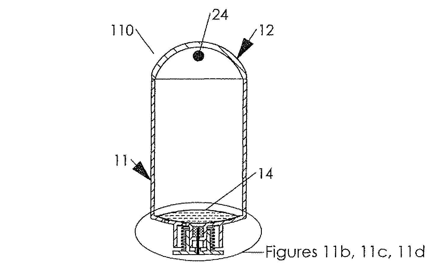
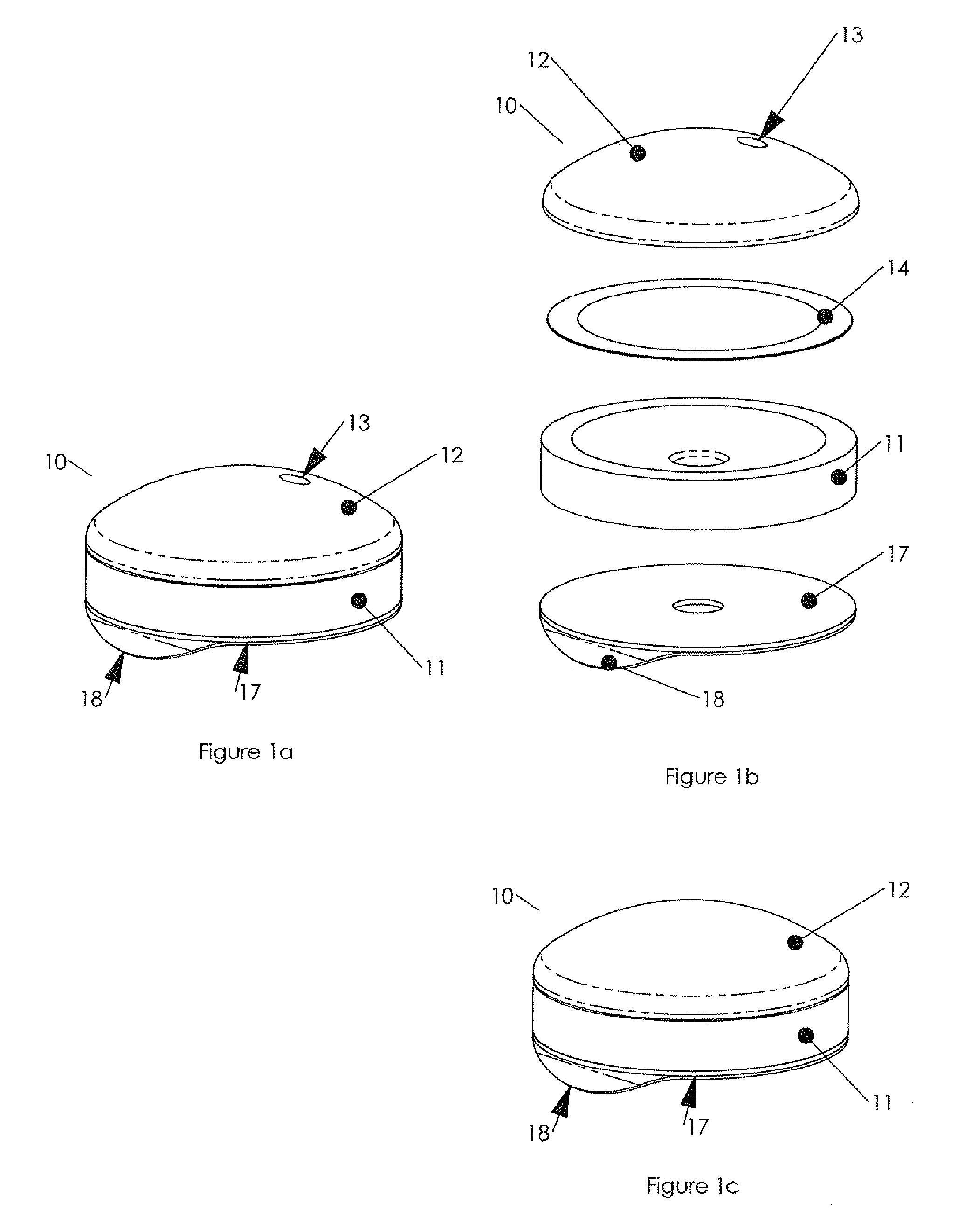
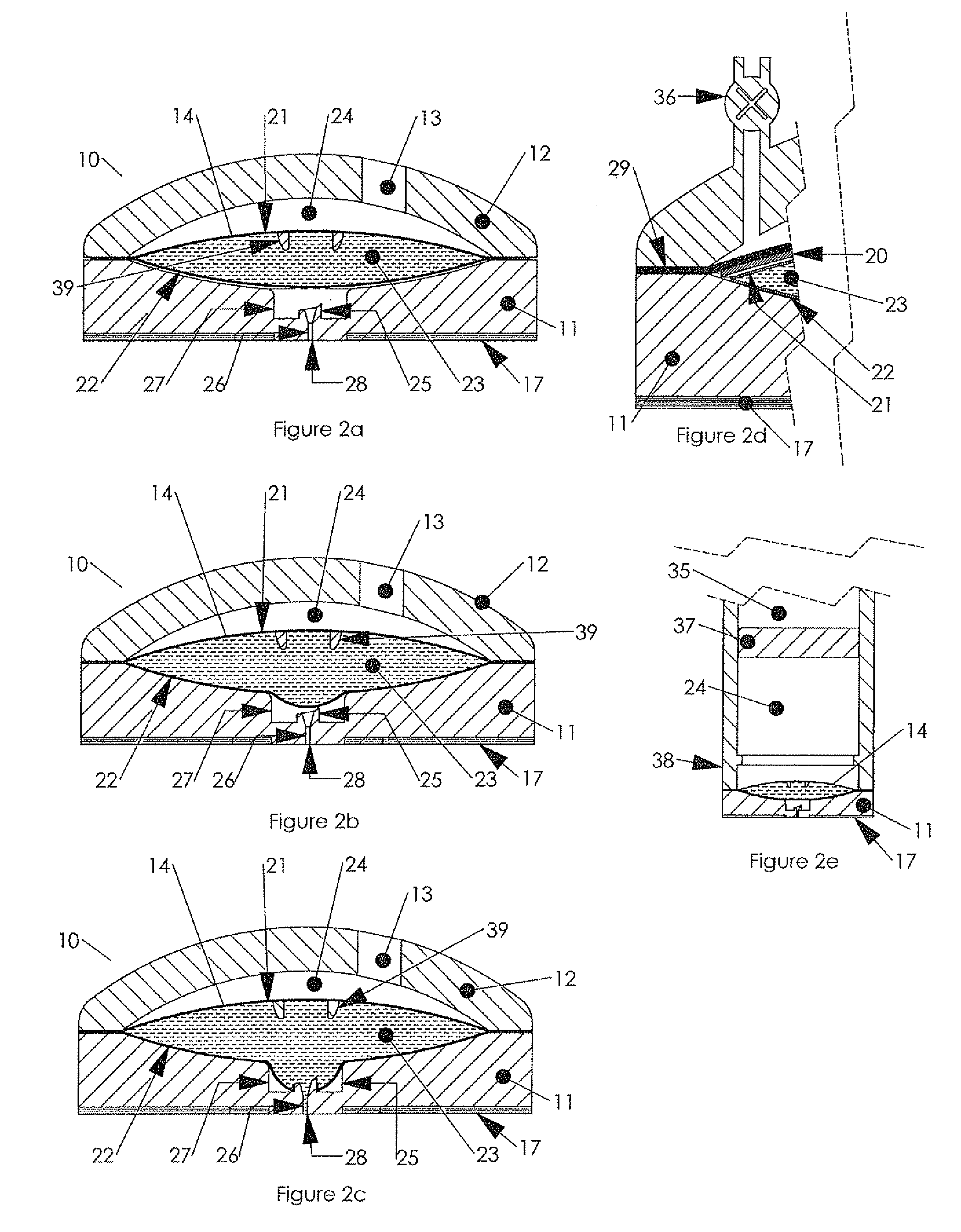
[0141]The seal between the cover 12 and the pouch 14 can be any sealing means known in the art including a) superior surface contact b) liquid tight press fit, c) glue, d) adhesive surface, e) a seal or an O-ring, f) welding the pouch 14 to the cover 12 by one of the heat joint means known in the art, or g) any other sealing means known in the art. In some embodiments the cover 12 is part of the reservoir 14 sub-assembly. In some embodiments the cover 12 is sealed directly to the base 11 defining the pressure chamber 24 in between these two parts. FIG. 2d demonstrates a further preferred embodiment of the apparatus of the present invention comprising, in addition to the elements of embodiment 10, a membrane 29 and a spring 20 in a form of a washer spring. In this embodiment the pressure chamber 24 is defined between the cover 12 and the membrane 29. One advantage of this embodiment is the separation of parts to function which allow optimization of each part design and materials to i...

embodiment 70

[0193]FIG. 7b demonstrates the embodiment 70 at an intermediate stage of pressurizing the reservoir. The pressure 24 is applied to the wall 21 which pressurizes the deliverable fluid 23 which in turn (since recess 27 is not pressurized) cause walls joint 62 to separate and allows the ingredient of compartment 71 to mix with the deliverable fluid 23.

[0194]Referring now to FIGS. 7c to 7e a further embodiment of the present invention is demonstrates where the multi compartment reservoir 14 assembly further comprises a flow conduit 78 which is separated by a sealed separable joint 79 from the deliverable fluid compartment 71. Conduit 78 leads to the administration device 28—in a form of hypodermic needle—via fluid conduit 26. The separable sealed joint 79 will separate under the presence of a threshold pressure value which is higher than the pressure threshold required for separating the joint 62. A drug delivery apparatus that utilize a separable sealed joint between a deliverable flui...

embodiment 130

[0218]Referring now to FIG. 13c a section view of embodiment 130 is demonstrated in the rest position. The two compartments of the pressurizing device 131 are clearly visible where the first compartment 134 contains a liquid ingredient 136 and the second compartment 135 contains granules of solid ingredients. In the rest position the content of the first compartment 134 and the second compartment 136 are isolated from each other by a sealed joint between the walls 132 and 133, such that interaction between the ingredients 135 and 137 is prevented, therefore pressure chamber 24 is not pressurized. Chamber 24 is defined by the cover 12 and moving plate 31. Moving plate 31 comprises a flat area for accommodating the pouch 14, having a central recess for receiving septum 113 and circumferential flexible section in a form of a bellows, said bellows allows an axial displacement of the flat central surface of the bellows under the presence of force. The moving plate 31 is made from a mater...


PUM


Abstract

A hypodermic drug delivery apparatus for delivering a pressurized medication fluid generally incorporates a reservoir containing at least one deliverable fluid, a reservoir pressurizing device, a rupturing member, a fluid administration device for communicating with the reservoir via a fluid passageway, and a rupture control mechanism for preventing rupture of a wall portion of the reservoir below a threshold pressure.

Description

BACKGROUND OF THE INVENTION[0001]1. Field of the Invention[0002]This invention related to a method and apparatus for storing and delivering drugs. More particular this invention relates to a method and apparatus where the drug is stored in, and delivered from, a pouch that is pressurized before delivery.[0003]2. Discussion of the Background[0004]Drug delivery technologies are becoming a critical part of the entire drug development process. Pharmaceutical companies are realizing the importance of drug delivery in the initial stages of drug development. The novel formulation of a drug by application of delivery technologies has opened many doors for the patients, physicians, as well as pharmaceutical companies. Moreover, drug delivery companies can offer new life to older drugs so that the drug can continue to generate more revenues for the pharmaceutical and biotechnology companies. New delivery methods also extend the product life of drugs going off patent, thus delaying the entry o...

Claims


Application Information

Patent Timeline
Patent Type & Authority Patents(United States)
IPC IPC(8): A61M37/00
CPCA61M5/2459A61M2005/3123A61M5/427A61M5/3287A61M5/286A61M5/2425A61M2037/0023A61M5/284A61M2005/314A61M31/002A61M5/282A61M5/2066A61M5/30A61M5/2466A61M37/0015A61M2005/3128A61M5/14248A61M5/2448A61M5/2033A61M5/322A61M5/2046A61M5/3234A61M5/31531A61M2005/3022
Inventor GENOSAR, AMIR
Owner AKTIVAX INC
Why Eureka
Try Eureka