
Operation monitoring system for processing apparatus

a monitoring system and processing apparatus technology, applied in the direction of electric controllers, instruments, ignition automatic control, etc., can solve the problems of large number of constituting parts of the apparatus, increased cost, and specific objects to be measured

Active Publication Date: 2014-04-01
ULVAC INC
View PDF13 Cites 3 Cited by
  • Summary
  • Abstract
  • Description
  • Claims
  • Application Information

AI Technical Summary

Benefits of technology

[0010]As described above, according to this invention, instead of measuring in advance the waveform of vibration at the time of abnormality of any one of the moveable parts, the soundness of the moveable parts can be easily judged out of the changes in the waveform of vibration corresponding to the specific event data whenever any one of the moveable parts is put into operation. Therefore, in case the waveform of vibration varies with the lapse of time, it becomes possible to monitor even the condition of deterioration of the moveable parts. In addition, since an arrangement is made that the vibrations of all the moveable parts that are operating within the range of transmission of the vibrations are detected and processed, the vibration detection means is not required for individual moveable parts, thereby attaining reduction in cost. Further, as compared with a case in which the information showing the state of each section of the processing apparatus is obtained at a certain cycle and is processed for monitoring the operation, the amount of data to be controlled can be made smaller. It is thus suitable as an operation monitoring system for a processing apparatus, such as cluster tools and the like, having relatively many moveable parts.
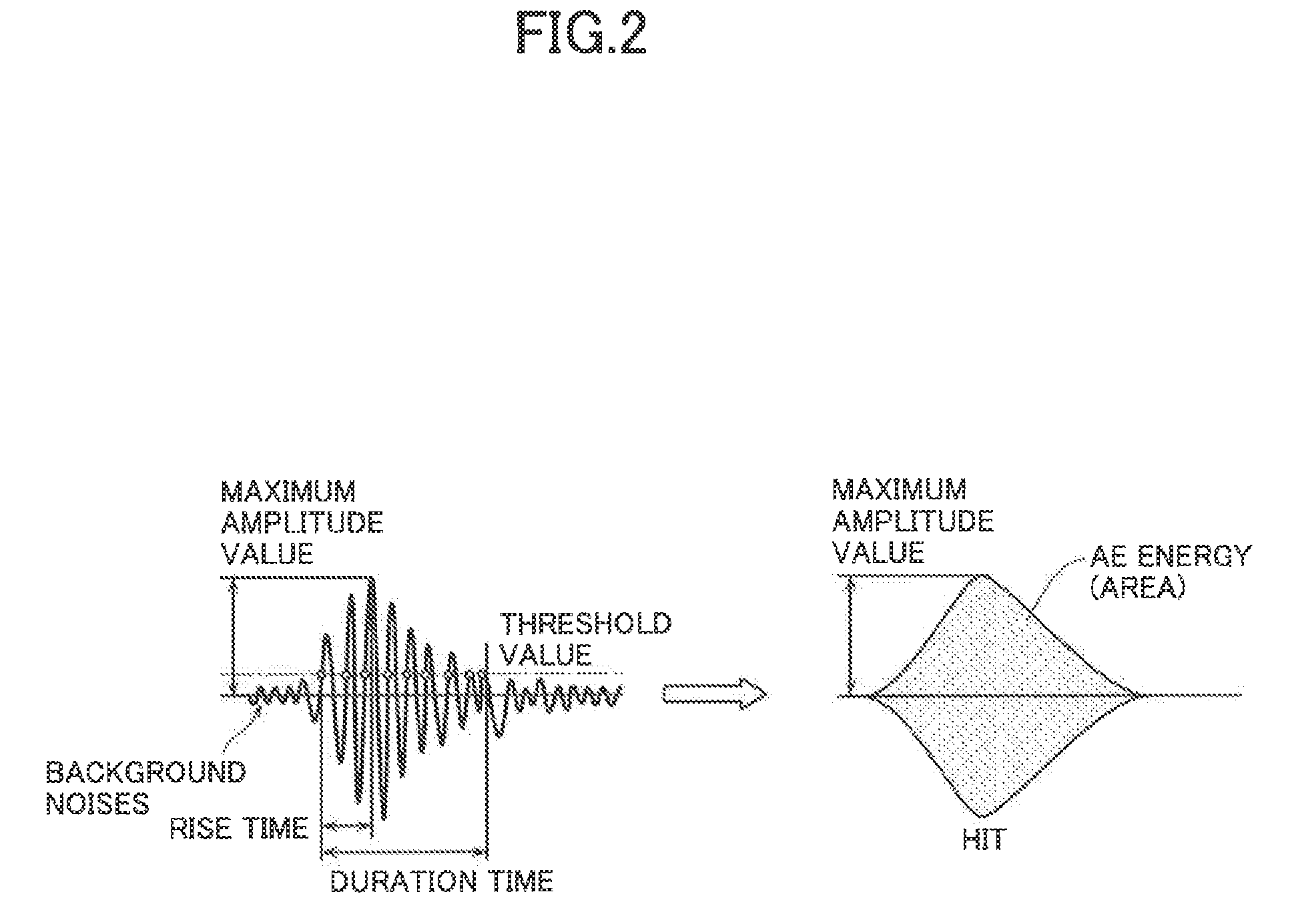
[0012]If an arrangement is made that the obtained waveform of vibration is stored in a memory or other known memory means after conversion to predetermined characteristics parameters, there is no need of storing a vast amount of data by storing the duration time, the rise time and the fall time of vibrations, maximum amplitude, vibration energy, peak frequency and the like, as compared with the case in which the data of waveforms of vibrations obtained are stored as they are. Further, the judgment of abnormality becomes easy.

Problems solved by technology

This solution, however, becomes large in the number of constituting parts of the apparatus.
In addition, the data to be controlled becomes vast in amount so that a high-performance control means becomes necessary, resulting in a higher cost.
Therefore, there is a problem in that the object to be measured becomes specific.
Further, since a judgment of abnormality is made only when a predetermined threshold value has been exceeded, it is not suitable for controlling the deterioration conditions of moveable parts that are subject to deterioration depending on the frequency of use.

Method used


Image

  • Operation monitoring system for processing apparatus
  • Operation monitoring system for processing apparatus
  • Operation monitoring system for processing apparatus

Examples


Embodiment Construction

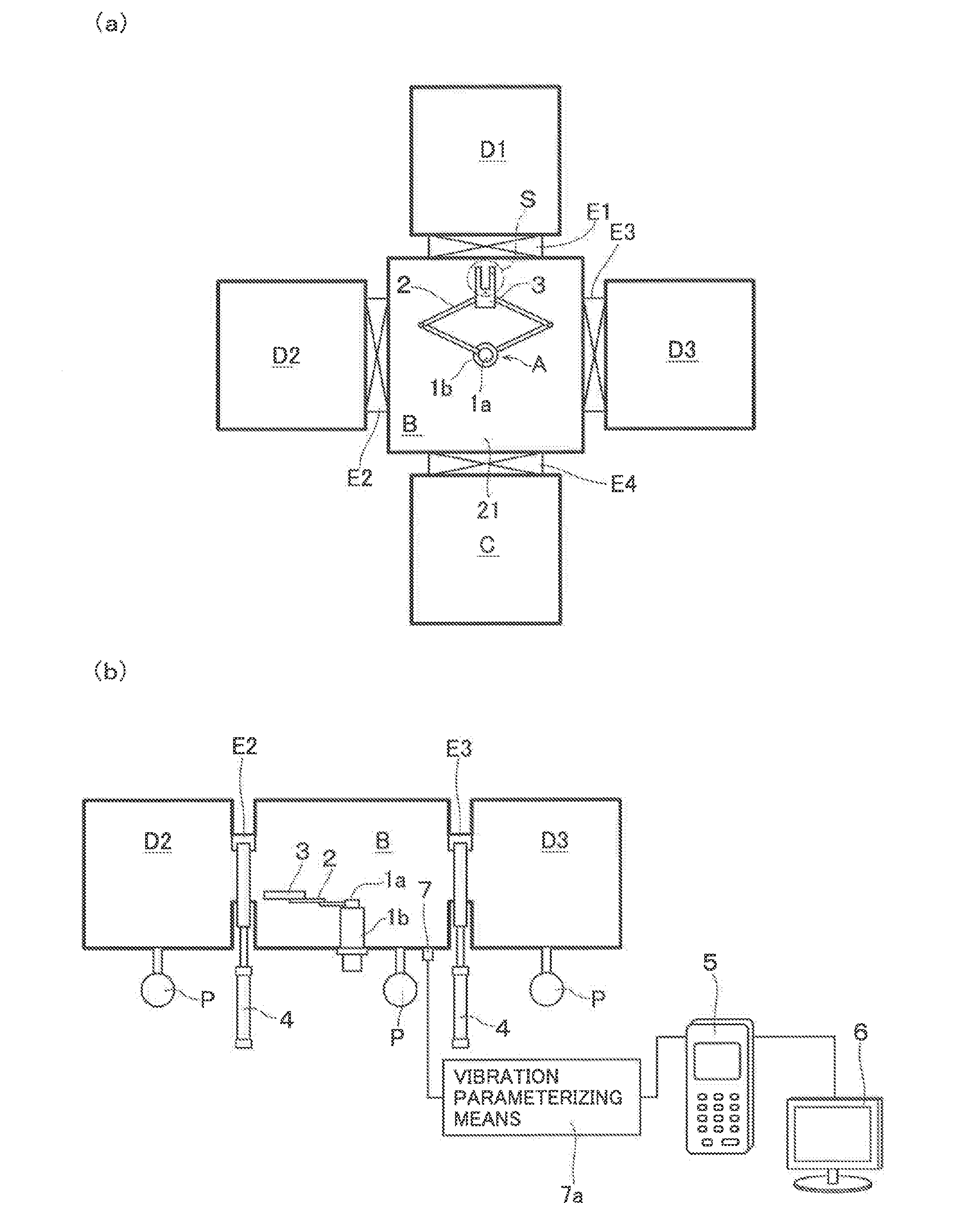
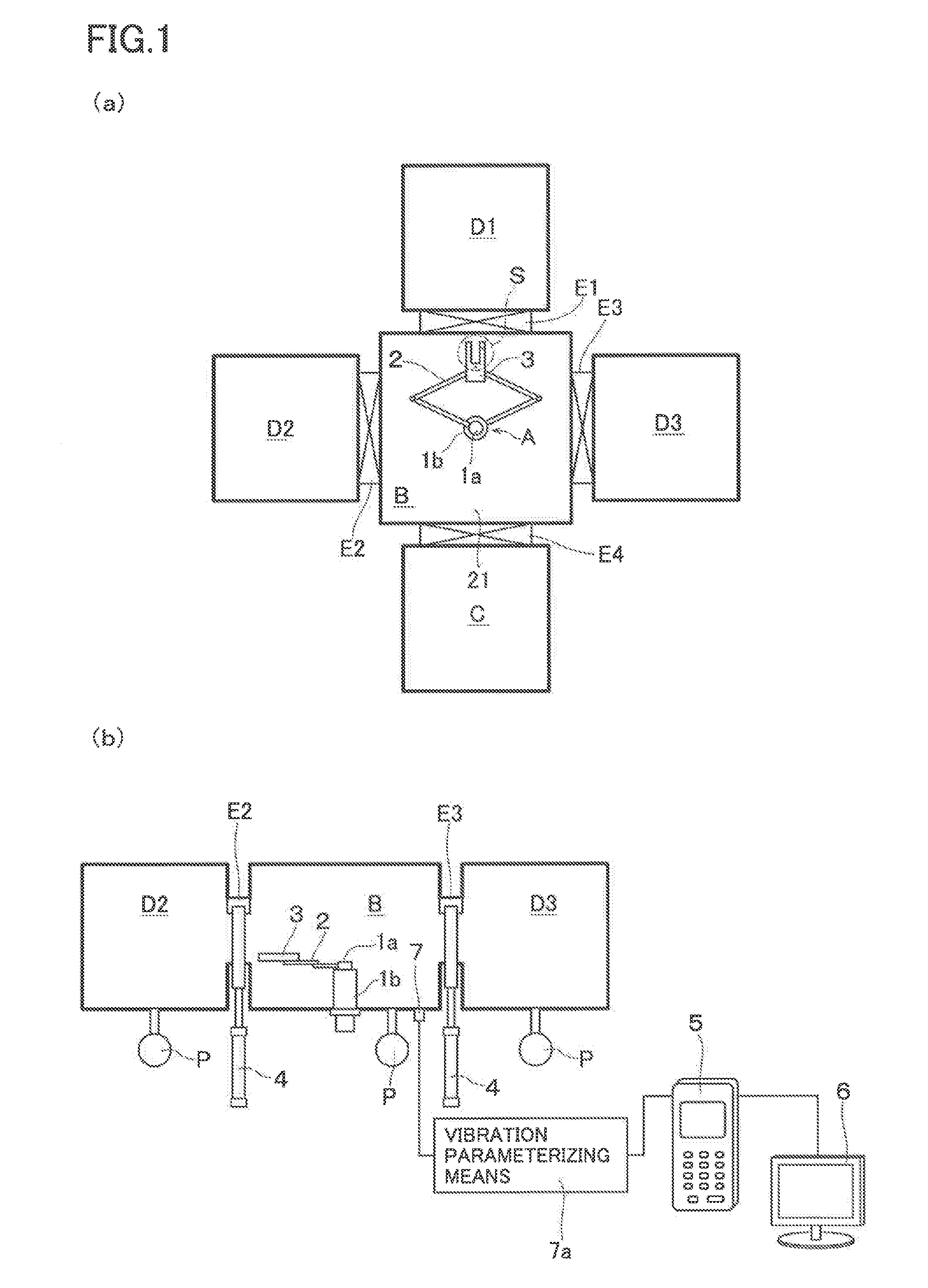
[0020]A description will now be made of an embodiment in which this invention is applied to a processing apparatus as shown in FIG. 1. In other words, a transfer chamber B is provided with a transfer robot A. The transfer robot A has two motors (not illustrated) as driving means. A coaxially disposed rotary shaft 1a, 1b of each of the motors has connected thereto a robot arm 2 to form a link mechanism. At the front end of the link mechanism there is mounted a robot hand 3. According to this arrangement, by appropriately controlling the rotational angle of the rotary shaft 1a, 1b of each of the motors, the robot arm 2 becomes telescopic and rotatable. It becomes thus possible to transfer the substrate S with the robot hand 3 to a predetermined position. The transfer chamber B is coupled to a load lock chamber C and processing chambers D1-D3 through gate valves E1-E4 that are provided with drive means 4 such as air cylinders and the like so that the chambers can be isolated from one a...


PUM


Abstract

In a processing apparatus having: moveable parts disposed to form a predetermined processing environment within a processing chamber in which a predetermined processing is performed on an object to be processed; and a control means for controlling the operation of each of the moveable parts, abnormality inclusive of deterioration with time of the moveable parts constituting the processing apparatus is made to be easily judged. There is provided a vibration detection means for detecting the waveforms of vibrations that occur accompanied by the operation of the moveable parts. When control is made from the control means in order to operate any one of the moveable parts, there are obtained event data corresponding to the control and the waveforms of vibrations of all the moveable parts that are operating simultaneously at the time in question. Each time the control corresponding to the event data is selected, or when a waveform of vibration corresponding to another event data of the same kind as that of the above-mentioned event data has been obtained, the change in the waveform is monitored. When the waveform has changed beyond a predetermined range, the processing apparatus is judged to be abnormal.

Description

[0001]This application is a national phase entry under 35 U.S.C. §371 of PCT Patent Application No. PCT / JP2009 / 003413, filed on Jul. 21, 2009, which claims priority under 35 U.S.C. §119 to Japanese Patent Application No. 2008-190629, filed Jul. 24, 2008, both of which are incorporated by reference.TECHNICAL FIELD[0002]The present invention relates to an operation monitoring system for a processing apparatus in which the operation of moveable parts constituting the processing apparatus can be monitored from the vibrations at the time of operation of the moveable parts.BACKGROUND ART[0003]As an apparatus for continuously performing various processes such as film-forming processing, etching processing, and the like on a substrate, there is known a processing apparatus (so-called cluster tool apparatus) which is arranged, as shown in FIG. 1; to dispose a load lock chamber C for a substrate S and a plurality of processing chambers D1-D3, through gate valves E1-E4 in a manner to enclose a...

Claims


Application Information

Patent Timeline
Patent Type & Authority Patents(United States)
IPC IPC(8): G06F19/00
CPCH01L21/67288H01L21/67742H01L21/67253B25J13/087H01L21/67276
Inventor FUJII, YOSHINORI
Owner ULVAC INC
Learn More