Compact aerosol sampler

Inactive Publication Date: 2014-04-08
GOVERNMENT OF THE UNITED STATES AS REPRESENTED BY THE SEC OF THE AIR FORCE
View PDF16 Cites 35 Cited by
  • Summary
  • Abstract
  • Description
  • Claims
  • Application Information

AI Technical Summary

Benefits of technology

[0015]means to rotate the fan and move aerosol through the sampler, so as to draw airborne particles through the inlet and through one or more nozzles, to impact the particles on the layer for analysis.
[0016]In a preferred embodiment, a pre-classifier 50 is mounted over the inlet 13 of the sampler 10, as shown in FIG. 3. The pre-classifier 50 screens out larger particles from entering such inlet, while the nozzles 20 of the impactor 18 below, control the lower limit of the size

Problems solved by technology

Also pumps are relatively heavy and noisy and require a relatively large battery pack to power same if one is to have a portable unit.
Also the pump is relatively loud and rather noticeable if worn indoors, to the discomfort of th

Method used


Image

  • Compact aerosol sampler
  • Compact aerosol sampler
  • Compact aerosol sampler

Examples


Embodiment Construction

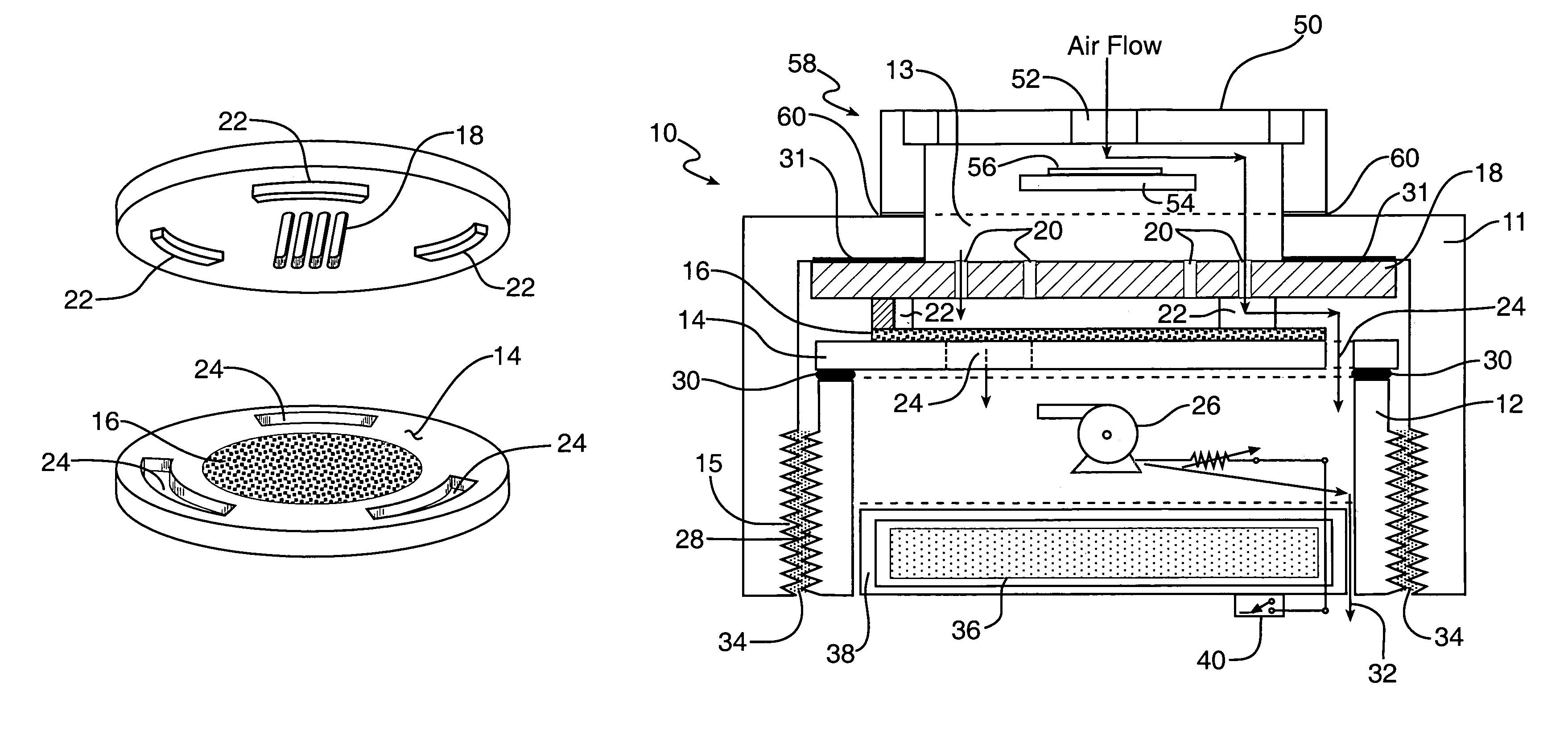
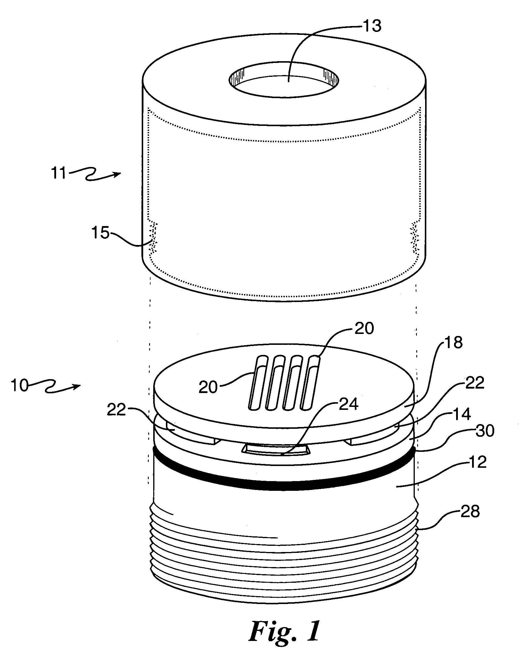
[0029]Referring now to the present invention in detail, aerosol sampler 10 has fan housing 12, surmounted by impaction plate 14, collection layer 16, impactor 18 and cap 11, having inlet 13, as shown in FIGS. 1, 2&3.

[0030]The impactor 18 has one or more nozzles 20 therein, which can each be, e.g., slits 200 microns wide and six centimeters long, for airflow into the air sampler assembly, as indicated in FIGS. 1, 2&3.

[0031]The incoming air is impacted through the nozzles 20 onto the collection layer 16, as indicated in FIGS. 1,2&3.

[0032]The underside of the impacting disk 18 has several feet or stand-offs 22 to keep the nozzles 20 spaced at a distance from the collection layer 16 and its underlying support, impaction plate 14, as shown or indicated in FIGS. 2 & 3. The nozzles preferably have sufficient size, in cross-section, to permit aerosol flow therethrough at low pressure drop.

[0033]In between the standoffs 22 is sufficient space for air to flow, at low-pressure drop, through th...


PUM


Abstract

Provided is an aerosol collector of reduced size having an aerosol inlet, an impactor plate containing several particle size-selecting nozzles therethrough, a replaceable collection layer and a fan having a power supply such as a battery pack, all of which fits a small container, attachable to, e.g., the lapel of the user, means to rotate the fan and move the aerosol through the sampler, so as to draw airborne particles through the inlet and through one or more nozzles, to impact the particles on the layer for analysis of same.

Description

STATEMENT OF GOVERNMENT INTEREST[0001]The invention described herein may be manufactured and used by or for the Government for governmental purposes without the payment of any royalty thereon.CROSS-REFERENCE TO RELATED PATENT APPLICATION[0002]This Application is a substitute for application Ser. No. 11 / 223,316, now abandoned, which was filed on Sep. 12, 2005, of the same title and inventor.FIELD OF THE INVENTION[0003]This invention relates to an aerosol sampler, particularly a compact aerosol sampler that is readily portable.BACKGROUND OF THE INVENTION[0004]Typically, prior art aerosol collection instruments use filters in which air is drawn therethrough by means of a pump. A pump is used because the pressure drop across a filter rises sharply with particle loading. However, pumps are suitable for moving air across a large pressure drop, though in relatively small amounts.[0005]Also pumps are relatively heavy and noisy and require a relatively large battery pack to power same if one...

Claims


Application Information

Patent Timeline
IPC IPC(8): G01N1/24
CPCG01N1/24G01N2001/245G01N1/2273
Inventor HEFF, ALLAN
Owner GOVERNMENT OF THE UNITED STATES AS REPRESENTED BY THE SEC OF THE AIR FORCE
Why Eureka
Try Eureka