Reinforced container system

a container system and reinforcement technology, applied in the field of packaging, can solve the problems of reducing the economic benefits of packaging, reducing the cost of packaging, and reducing the efficiency of packaging, so as to achieve the effect of maximizing the package economy

Active Publication Date: 2014-04-08
INT PAPER CO
View PDF22 Cites 19 Cited by
  • Summary
  • Abstract
  • Description
  • Claims
  • Application Information

AI Technical Summary

Benefits of technology

[0004]The reinforced container system of the present invention can reliably survive the tremendous forces and inertia for an extended period of time caused by mixing / shaking machinery without additional protection and to maximize the economy of the package and add an additional safeguard in the case of a package which may have been in some way pre-abused prior to insertion into the mixing machine.
[0005]The reinforced container system of the present invention includes a lightweight, collapsible, re-usable protective sleeve that can be used at, for instance, a paint retail store, to house a bag-in-box package that contains, for instance, 1-5 gallons of paint. This sleeve is utilized during the use of commonly available mechanical mixing machinery and is removed from the main paint package by a retail worker prior to product's store departure. It is previously determined that an octagonally-shaped container optimizes all desired physical and economic attributes for such a retail package. Thus, protective sleeve for this container is accordingly shaped to accommodate that exact shape. Some very important features of the protective sleeve are: 1) lightweight fracture-resistant materials used such as plastic resins, aluminum or graphite fiber, 2) further light-weighting due to weight-reduction holes in the side-walls so that it reduces electrical load on mixing machineries, 3) a geometry which allows placement of the sleeve over the top of a heavy package and details (i.e.; finger holes) which then allow it to be removed from the top, without requiring lifting of the main package / box, 4) hinged and / or foldable collapsibility features which allow the sleeve to be stored without consuming too much valuable retail storage space or counter space, when it is not used, 5) maximum surface contact between all container outer vertical panels and all corresponding sleeve inner vertical walls (form-fitting), 6) Sleeve height being slightly less than container height, so that mixing machinery holding platens can apply adequate pressure to the container, such that the entire bag-in-box is secured in the machinery throughout the entire liquid mixing process.
[0007]Accordingly, one aspect of the present invention is directed to a reinforced container system comprises a container having a bottom wall, a pair of opposite side walls, a pair of opposite end walls, and opposed pairs of diagonal corner panels interposed between adjacent side and end walls to form an interior space. The bottom wall, the side walls, the end walls and the diagonal corner panels are joined to one another along vertical folds. The bottom wall includes two opposed glue panels each of which is foldably joined to respective longitudinal edges of the bottom wall and each of which attached to the respective side walls. A protective sleeve is configured to detachably attach to the container. The protective sleeve includes two side walls, two end walls and opposed pairs of diagonal corner walls interposed between adjacent side and end walls. The side walls, the end walls and the diagonal corner walls are joined to one another along four vertical hinges to whereby protect the container against tremendous forces and inertia caused by mixing or shaking machinery.
[0008]Another aspect of the present invention is directed to a reinforced container system comprises a container having a bottom wall, a pair of opposite side walls, a pair of opposite end walls, and opposed pairs of diagonal corner panels interposed between adjacent side and end walls. The bottom wall, the side walls, the end walls and the diagonal corner panels are joined to one another along vertical folds to form an interior space. The bottom wall includes two opposed glue panels each of which foldably joined to respective longitudinal edges of the bottom wall and each of which attached to the respective side walls. A liner insert is disposed in the container and is fitting closely in the container sidewalls and bottom wall in an overlapping relationship. A plastic bag is disposed in the interior space of the container and is confined within the liner insert in which the plastic bag includes a spout for flowable material. A protective sleeve is configured to detachably attach to the outer wall of the container. The protective sleeve includes two opposed side walls having inner surfaces, two opposed end walls and opposed pairs of diagonal corner walls interposed between adjacent side and end walls. The side walls, the end walls and the diagonal corner walls are joined to one another along four vertical hinges to whereby protect the container against tremendous forces and inertia caused by mixing or shaking machinery.
[0009]One further aspect of the present invention is directed to a reinforced container system comprises a container having a bottom wall, a pair of opposite side walls, a pair of opposite end walls, and opposed pairs of diagonal corner panels interposed between adjacent side and end walls. The bottom wall, the side walls, the end walls and the diagonal corner panels are joined to one another along vertical folds to form an interior space. The bottom wall includes two opposed glue panels each of which is foldably joined to respective longitudinal edges of the bottom wall and each of which attached to the respective side walls. A liner insert is disposed in the container and is fitting closely in the container sidewalls and bottom wall in an overlapping relationship. The liner insert is substantially coextensive in height with the container side walls and diagonal corner panels. A plastic bag is disposed in the interior space of the container and is confined within the liner insert. The plastic bag includes a spout for flowable material. A protective sleeve is configured to detachably attach to the outer wall of the container. The protective sleeve includes two opposed side walls having inner surfaces, two opposed end walls and opposed pairs of diagonal corner walls interposed between adjacent side and end walls. Two retaining plates each of which is attached to the respective inner surface of the side walls and aligned with the respective top edge of each side wall of the sleeve and extend downwardly therefrom. The side walls, the end walls and the diagonal corner walls are joined to one another along four vertical hinges to whereby protect the container against tremendous forces and inertia caused by mixing or shaking machinery.

Problems solved by technology

Any package placed inside commercial paint mixing / shaking machinery is subjected to tremendous forces and inertia for an extended period of time.
A bag-in-box, although having significant economic and environmental impact advantages over a traditional round rigid plastic pail, is obviously more vulnerable to the abuses such machinery generates.
Each of these methods, while effective in providing reinforcement, may be undesirable for one or more reasons, such as increased material and / or manufacturing costs (such as the sesame tape), or increased overall operational costs and / or setup time / steps.

Method used


Image

  • Reinforced container system
  • Reinforced container system
  • Reinforced container system

Examples


Embodiment Construction

[0019]While this invention is susceptible of embodiment in many different forms, there is shown in the drawings and will herein be described in detail preferred embodiments of the invention with the understanding that the present disclosure is to be considered as an exemplification of the principles of the invention and is not intended to limit the broad aspect of the invention to the embodiments illustrated. In the present invention the use of prime character in the numeral references in the drawings directed to the different embodiment indicate that those elements are either the same or at least function the same.

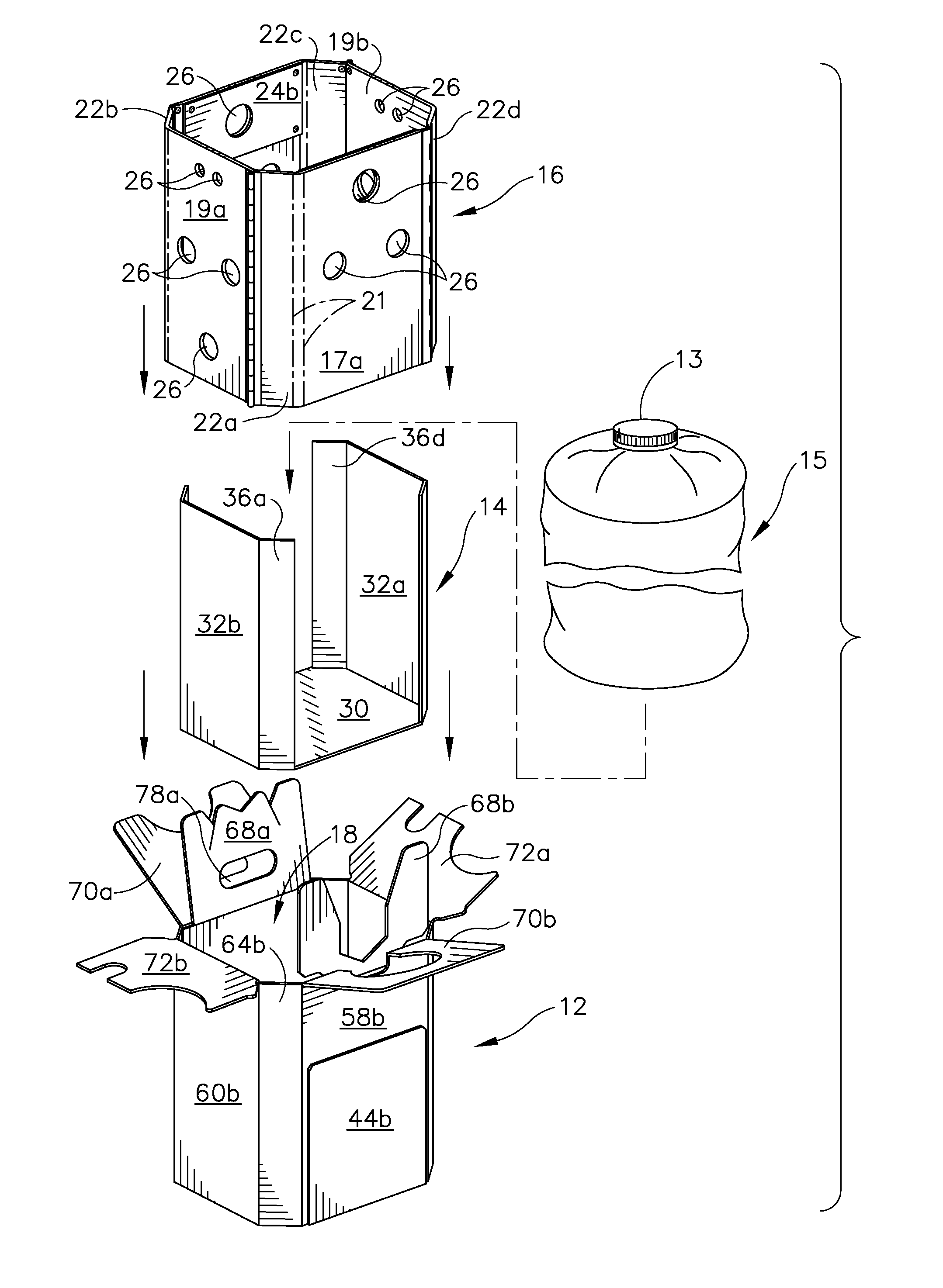
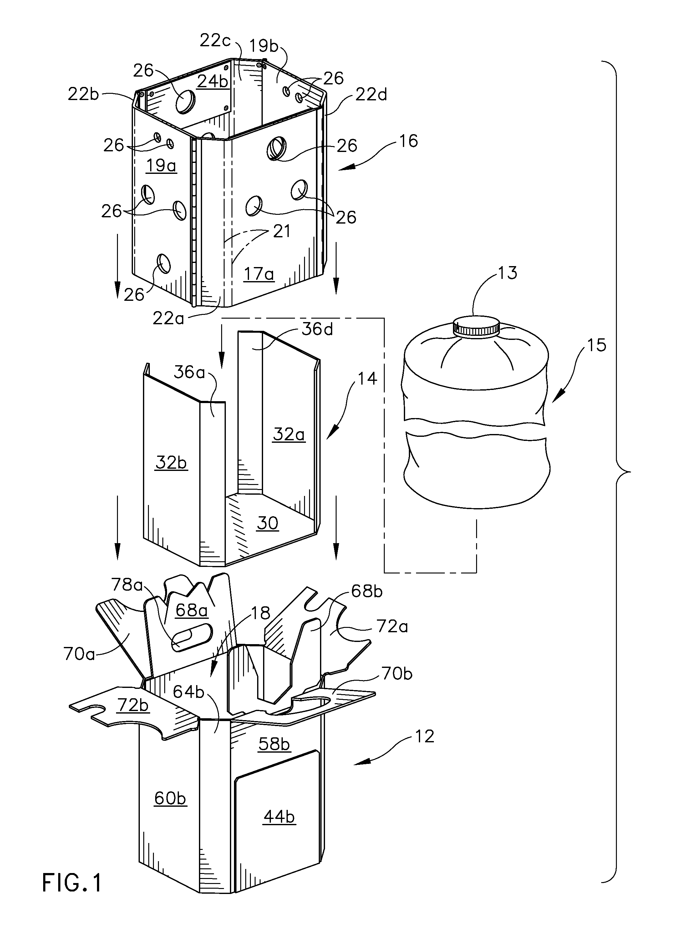
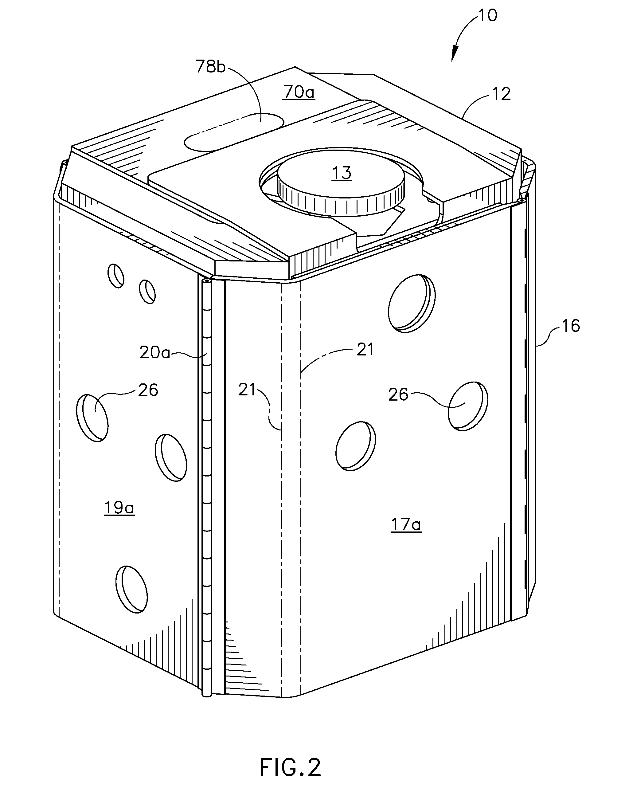
[0020]FIG. 1 is an exploded perspective view of a reinforced container system 10 which is shown in an assembled form in FIG. 2 in accordance to the preferred embodiment of the invention. The reinforced container system 10 comprises a container 12, a liner insert 14, a bag 15, and a protective sleeve 16. The liner insert 14 is snugly fit into an interior space 18 and the p...


PUM


Abstract

A reinforced container system comprises a container having a bottom wall, a pair of opposite side walls, a pair of opposite end walls, and opposed pairs of diagonal corner panels interposed between adjacent side and end walls to form an interior space. The bottom wall includes two opposed glue panels each of which is foldably joined to respective longitudinal edges of the bottom wall and each of which attached to the respective side walls. A protective sleeve is configured to detachably attach to the container. The protective sleeve includes two side walls, two end walls and opposed pairs of diagonal corner walls interposed between adjacent side and end walls. The side walls, the end walls and the diagonal corner walls are joined to one another along four vertical hinges to whereby protect the container against tremendous forces and inertia caused by mixing or shaking machinery.

Description

FIELD OF THE INVENTION[0001]The present invention relates generally to packaging for shipping and storing flowable products. A thin plastic inner bag for the liquid is placed within a reinforced corrugated container system for structural rigidity and protection. The reinforced container system is particularly suitable for products such as paints that must be severely agitated in the container to disperse and homogenize the contents before use.BACKGROUND OF THE INVENTION[0002]Corrugated paperboard containers are used to store and transport a variety of goods. It has been common practice for many years to ship liquid materials contained within plastic bags enclosed. Corrugated paperboard containers are used to contain a flexible plastic inner container, also known as bag-in-box, with a pull-up spout for filling and dispensing the liquid contents. Any package placed inside commercial paint mixing / shaking machinery is subjected to tremendous forces and inertia for an extended period of ...

Claims


Application Information

Patent Timeline
Patent Type & Authority Patents(United States)
IPC IPC(8): B65D5/62
CPCB65D5/566B65D77/065
Inventor PHILIPS, NICHOLAS A.KUHN, WAYNE H.
Owner INT PAPER CO
Why Eureka
Try Eureka