Fixing mechanism for storage device

a fixing mechanism and storage device technology, applied in the direction of lighting support devices, electric apparatus casings/cabinets/drawers, instruments, etc., can solve the problems of high labor cost, complex production procedure, and inability of users and manufacturers to quickly interchange dasds, so as to save labor and time cost, simplify the structure of the fixing mechanism of the storage device, and simplify the effect of installation/removal of the storage devi

Inactive Publication Date: 2014-04-08
LITE ON ELECTRONICS (GUANGZHOU) LTD +1
View PDF6 Cites 7 Cited by
  • Summary
  • Abstract
  • Description
  • Claims
  • Application Information

AI Technical Summary

Benefits of technology

[0009]Therefore, an object of the present invention is to provide a fixing mechanism for storage device that can alleviate the aforesaid drawbacks of the prior art.
[0016]In view of the above, the present invention has the following beneficial effects. With the design that the latch member can be pressed / released through the displacement of the detent component along the slide direction and thus make the latch member lock / unlock the storage device. Accordingly, a user can install or remove the storage device without using any screw or hand tool, so that the installation / removal of the storage device is dramatically simplified, and the labor and time cost are greatly saved. Furthermore, in the present invention, the structure of the storage device fixing mechanism is simple, and thus the space occupied by the fixing mechanism and the manufacturing cost thereof can be reduced.

Problems solved by technology

However, a problem facing the industry is the inability of users and manufacturers to quickly interchange DASDs.
For personal computer (PC) manufactures and users, this is a problem which leads to a complex production procedure and a high labor cost, and also affects the production efficiency.
Additionally, as the number of the screws is large and the size thereof is small, some of the screws may be left inside the computer housing, contact the circuit board and cause short circuit.

Method used


Image

  • Fixing mechanism for storage device
  • Fixing mechanism for storage device
  • Fixing mechanism for storage device

Examples


first embodiment

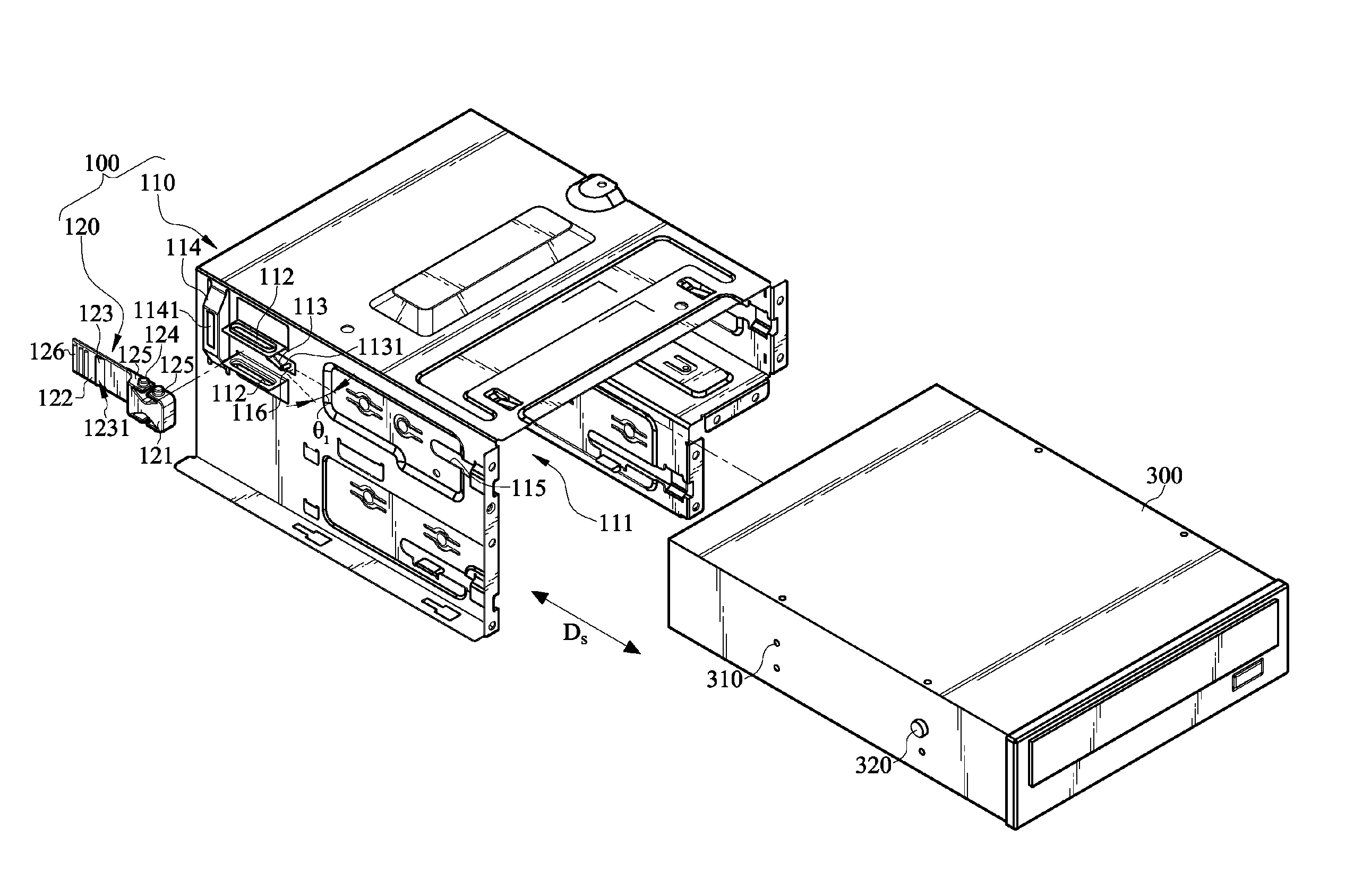
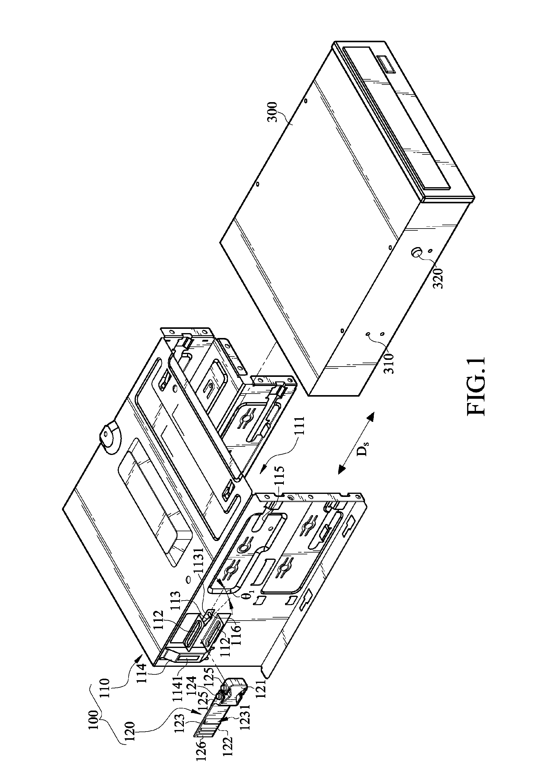
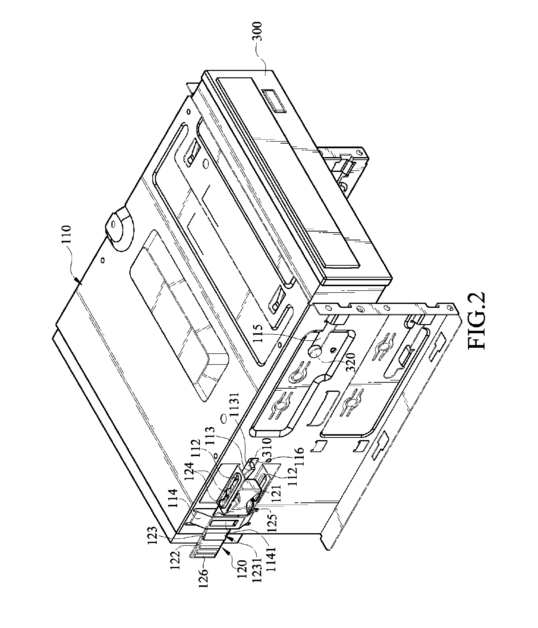
[0034]FIG. 1 is an exploded view of a fixing mechanism and a storage device according to the present invention and FIG. 2 is a three-dimensional view of the combination of the fixing mechanism and the storage device in FIG. 1. A fixing mechanism 100 is provided for fixing a storage device 300 in an electronic device, such as a computer. The fixing mechanism 100 is mounted on the computer housing. At least one side of the storage device 300 has a fixing hole 310.

[0035]The fixing mechanism 100 comprises a frame 110 and a detent component 120. The frame 110 is, for example, a drive bracket and is substantially in a π-shaped structure. Therefore, an accommodating space 111 is formed in the frame 110 to receive the storage device 300. Preferably, one sidewall of the frame 110 is recessed toward the accommodating space 111, so that the storage device 300 can be installed thereon to avoid dropping or offsetting from its preset position. A slide slot 115 having an open end and a closed end ...

second embodiment

[0056]In the second embodiment, the fixing mechanism 200 comprises a frame 210 and a detent component 220. The frame 210 is, for example, a drive bracket, and an accommodating space 211 is formed inside the frame 210 to receive a storage device 300.

[0057]At least one sidewall of the frame 210 is disposed with a slide slot 214 which has an open end and a closed end. A guide component 320 is screwed on one side of the storage device 300 and corresponding to the slide slot 214, and is capable of sliding in the slide slot 214 of the frame 210.

[0058]As shown in FIG. 6 and FIG. 7, at least one sidewall of the frame 210 has a plurality of fasteners 212 and a latch member 213. In this embodiment, the fasteners 212 are arranged in two parallel rows and disposed in pairs. That is, each fastener 212 in an upper row matches with one fastener 212 in a lower row, and the fasteners 212 are disposed at intervals. It should be noted that, in some embodiments, the fasteners 212 are arranged in two pa...


PUM


Abstract

A fixing mechanism for storage device includes a frame, and a detent component. One sidewall of the frame has a latch member. The detent component is movably disposed on the sidewall of the frame, and has a pressing component and an operating component. The operating component is disposed with at least one stop block. When the operating component is moved relative to the frame to a press position, the pressing component pushes the latch member to engage with the storage device, the stop block is embedded in the frame, and the detent component is held in the press position. Accordingly, the storage device may be fixed to the frame rapidly without using any screw, the operating procedure is dramatically simplified, and the space occupied by the fixing mechanism and the manufacturing cost are reduced.

Description

CROSS-REFERENCE TO RELATED APPLICATIONS[0001]This non-provisional application claims priority under 35 U.S.C. §119(a) on Patent Application No(s). 099218496 filed in Taiwan, R.O.C. on Sep. 24, 2010, the entire contents of which are hereby incorporated by reference.BACKGROUND OF THE INVENTION[0002]1. Field of the Invention[0003]The present invention relates to a fixing mechanism, and more particularly to a fixing mechanism for installing a storage device in a computer housing without using any screw.[0004]2. Description of Related Art[0005]Personal computers (PC) typically employ Direct Access and Storage Devices (DASDs) such as hard disk drives (HDD) and optical disk drives (ODD). These devices are typically maintained in the mechanical chassis of a computer housing. This configuration includes a DASD that slides into or is bolted to the mechanical chassis of the computer housing.[0006]However, a problem facing the industry is the inability of users and manufacturers to quickly inte...

Claims


Application Information

Patent Timeline
Patent Type & Authority Patents(United States)
IPC IPC(8): G06F1/16H05K7/16
CPCG06F1/187G11B33/124
Inventor KUO, PO-HSIULIU, CHIH-LILIU, YUNG-LUNGTSENG, CHUAN-CHIEH
Owner LITE ON ELECTRONICS (GUANGZHOU) LTD
Why Eureka
Try Eureka