Electric load driving circuit

a driving circuit and load technology, applied in the direction of dc source parallel operation, amplifiers, semiconductor devices/discharge tubes, etc., can solve the problems of inability to drive the load the voltage applied to the load cannot be raised to the terminal voltage of the capacitor or higher, and the load cannot be driven properly. to achieve the effect of more efficient electric load driving

Active Publication Date: 2014-04-08
SEIKO EPSON CORP
View PDF8 Cites 2 Cited by
  • Summary
  • Abstract
  • Description
  • Claims
  • Application Information

AI Technical Summary

Benefits of technology

[0010]An advantage of some aspect of the invention is to provide an electric load driving circuit which enables efficient and stable driving of an electric load having a capacity component while switching capacitors.
[0012]In such an electric load driving circuit according to this aspect of the invention, a capacitor is provided parallel to each of the power sources generating different voltages and the capacitors have different terminal voltages from each other. As the connection between these capacitors and the electric load is switched, a voltage is applied to the electric load. That is, if a capacitor having a high terminal voltage is connected to the electric load, a high voltage is applied to the electric load. On the other hand, if a capacitor having a low terminal voltage is connected to the electric load, a low voltage is applied to the electric load. Each capacitor is provided with a discharge path capable of discharging electric charges without having to discharge via the electric load. Therefore, the quantity of electric charges discharged through each discharge path can be controlled.
[0014]However, depending on the voltage waveform applied to the electric load, this balance may be lost and the quantity of electric charges stored in the capacity may increase, causing a rise in the terminal voltage. Even in such cases, since the electric load driving circuit according to this aspect of the invention is provided with a discharge path for each capacitor, excessive electric charges are discharged not via the electric load and the rise in the terminal voltage of each capacitor is thus prevented. Therefore, switching the capacitors enables driving the load having the capacity component efficiently and stably.
[0016]Thus, if the terminal voltage of the capacitor is raised, electric charges can be immediately discharged and the terminal voltage can be lowered. Moreover, excessive discharge of electric charges and hence excessive reduction in the terminal voltage can be avoided. Consequently, it is possible to supply an accurate voltage waveform and properly drive the electric load.
[0018]If the voltage waveform to apply to the electric load is predetermined, the quantity of electric charges stored in each capacitor can be estimated in advance, and when and how much electric charge should be discharged can be predicted. Therefore, by thus performing control to discharge the quantity of electric charges that is predicted in accordance with the voltage waveform to be applied, it is possible to avoid a rise in the terminal voltage of each capacitor and to drive the electric load with an accurate voltage waveform.
[0020]Even if one capacitor has excessive electric charges, another capacitor may lack electric charges. In such a case, if the discharge path of the capacitor having excessive electric charges is configured to be capable of discharging electric charges to the capacitor lacking electric charges, the excessive electric charges can be supplied to the other capacitor and therefore there is no need to supply electric charges from the power source. Consequently, the electric load can be driven more efficiently.

Problems solved by technology

Of course, if the applied voltage to the load exceeds the terminal voltage of the capacitor, electric charges cannot be supplied from the capacitor.
Therefore, the applied voltage to the load cannot be raised to the terminal voltage of the capacitor or higher.
However, with the proposed technique, there are cases where the terminal voltage of a capacitor gradually rises while a voltage is applied to drive the load, making proper driving of the load difficult.
However, depending on the voltage waveform applied to the electric load, this balance may be lost and the quantity of electric charges stored in the capacity may increase, causing a rise in the terminal voltage.
Even if one capacitor has excessive electric charges, another capacitor may lack electric charges.

Method used


Image

  • Electric load driving circuit
  • Electric load driving circuit
  • Electric load driving circuit

Examples


first modified embodiment

C-1. First Modified Embodiment

[0059]In the above embodiment, it is assumed that when the electric load 200 with a low applied voltage is connected to a capacitor, the discharge circuit 142 of that capacitor is made to operate. However, the timing of making the discharge circuit 142 to operate and discharge electric charges is not limited to the above timing.

[0060]For example, if a slower voltage waveform is applied, as shown in FIG. 7A, the electric load 200 may be connected to one capacitor for a long period of time. In such a case, the discharge circuit 142 may be made to operate only during a partial period of the period when the capacitor is connected to the electric load 200. In this case, a large quantity of electric charges flows into the capacitor for a while after the switch is changed over and the electric load 200 is connected to the capacitor. Therefore, the discharge circuit 142 may be made to operate during this period alone.

[0061]Moreover, the discharge circuit 142 ma...

second modified embodiment

C-2. Second Modified Embodiment

[0063]In the above embodiment and the first modified embodiment, it is assumed that the voltage generated by each power source has a substantially equal voltage difference. However, the voltage generated by each power source need not necessarily be set with an equal voltage difference. Moreover, the generated voltage may be changeable.

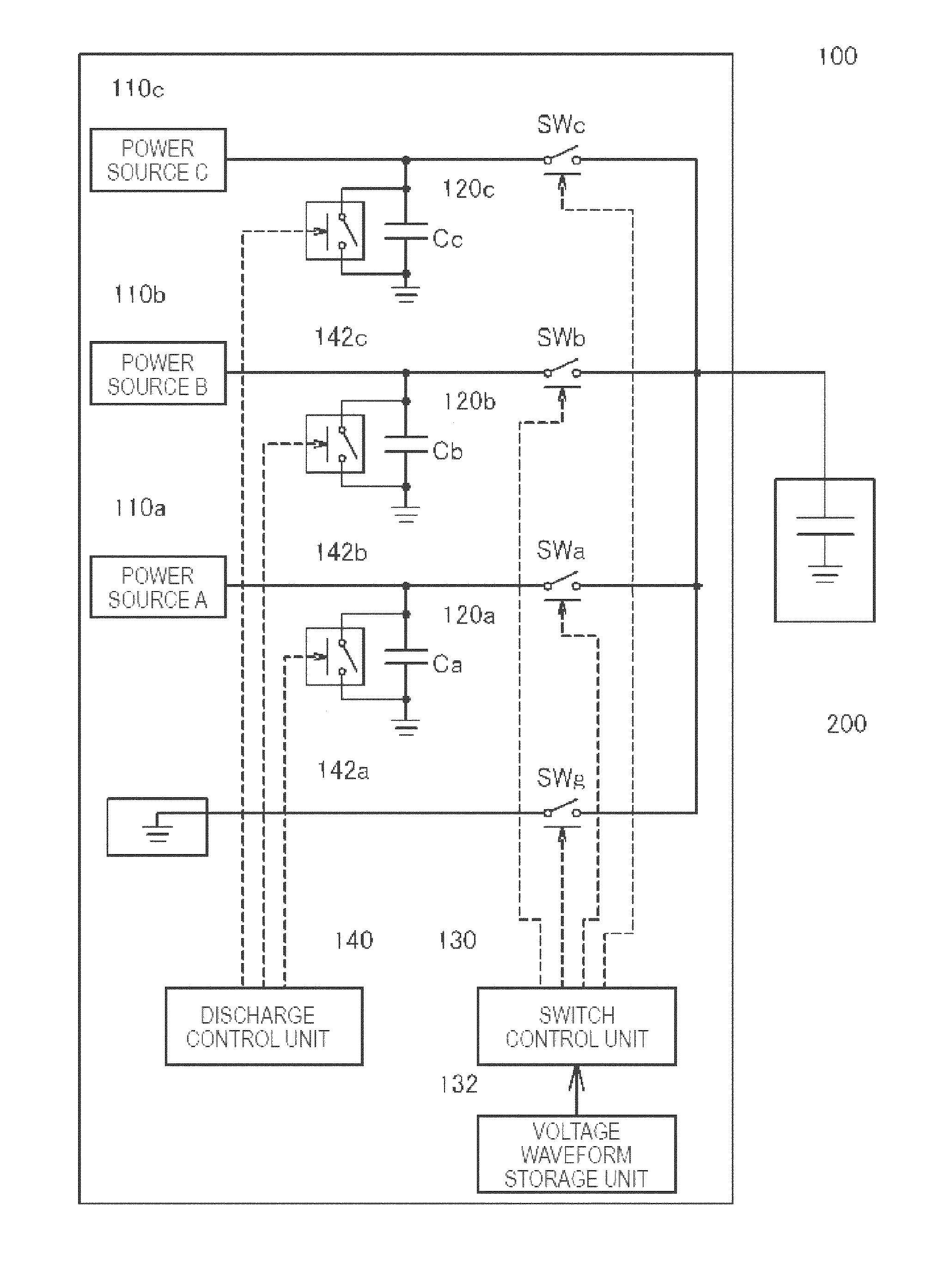
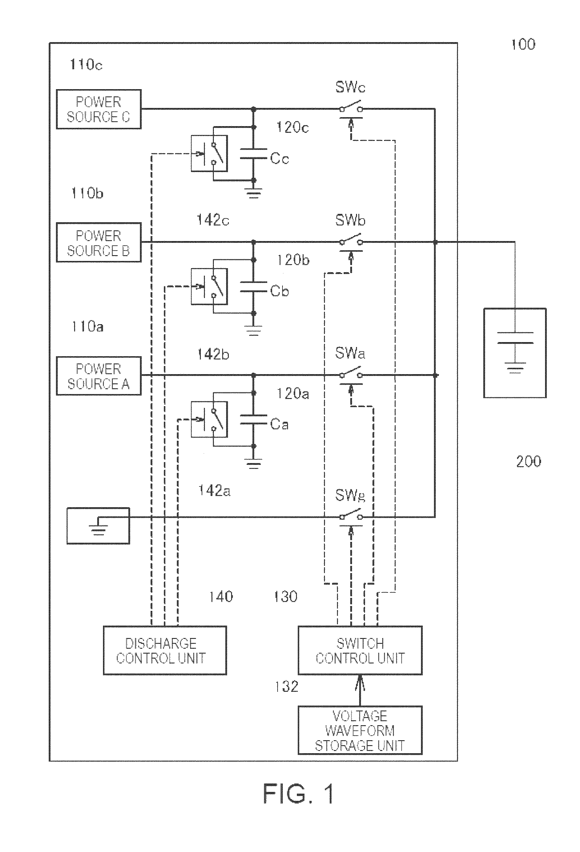
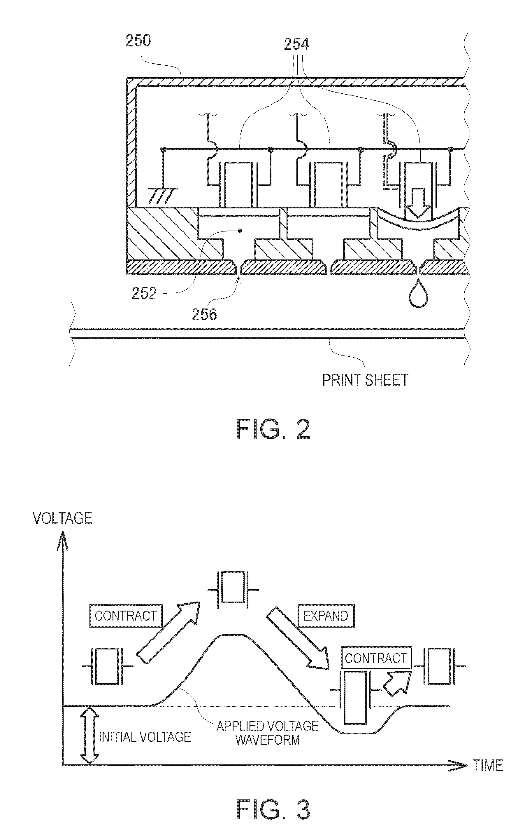
[0064]FIG. 8A and FIG. 8B show an example of driving the electric load 200 by using a voltage waveform in which the voltage difference between the voltage Vb generated by the power source 110b (power source B shown in FIG. 1) and the voltage Vc generated by the power source 110c (power source C shown in FIG. 1) is set to be broader than the other voltage differences between power sources (for example, the voltage difference between Va and Vb, or the voltage difference between GND and Va). For example, in the ink jet printer, ink that is temporarily sucked into the ink chamber 252 is pushed out and ink droplets are ejected...

third modified embodiment

C-3. Third Modified Embodiment

[0067]In the above embodiment and first and second modified embodiments, it is assumed that any of the discharge circuits 142 discharges electric charges accumulated in the capacitor 120 to the ground. However, electric charges may be discharged to another capacitor having a lower terminal voltage, instead of the ground.

[0068]FIG. 9 is an explanatory view showing an electric load driving circuit according to a third modified embodiment in which excessive electric charges accumulated in a capacitor are discharged to another capacitor. In the example shown in FIG. 9, if excessive electric charges are accumulated in the capacitor 120c, the electric charges can be discharged to the capacitor 120b via the discharge circuit 142c. If excessive electric charges are accumulated in the capacitor 120b, the electric charges can be discharged to the capacitor 120a via the discharge circuit 142b. Each of the discharge circuits 142a, 142b and 142c is provided with a s...


PUM


Abstract

An electric load driving circuit for driving an electric load having a capacity component includes a plurality of power sources generating different voltages, capacitors provided parallel to the plurality of power sources, a switch control unit that switches connections between the capacitors and the electric load and thereby switching a voltage applied to the electric load, discharge paths that enable discharging electric charge stored in the capacitor, and a discharge control unit that controls a quantity of electric charge discharged from the discharge paths.

Description

[0001]This application claims priority to Japanese Patent Application No. 2008-275234 filed on Oct. 27, 2008, and the entire disclosure thereof is incorporated herein by reference.BACKGROUND[0002]1. Technical Field[0003]The present invention relates to a technique of applying a predetermined voltage waveform to an electric load having a capacity component and thus driving the electric load.[0004]2. Related Art[0005]Various types of electric loads driven by the application of a voltage are known and there are a number of electric loads having a capacity component such as a so-called piezoelectric element and a liquid crystal screen. In an electric load having a capacity component, the applied voltage rises as electric charges are supplied to the load, whereas the applied voltage decreases as electric charges are discharged from the load. Therefore, if a capacitor is used when driving a load having a capacity component, the load can be efficiently driven. That is, in the case of lower...

Claims


Application Information

Patent Timeline
Patent Type & Authority Patents(United States)
IPC IPC(8): H02J1/10
CPCB41J2/04581B41J2/04541B41J2/14274B41J2/04588
Inventor YOSHINO, HIROYUKIAZAMI, NOBUAKIMIYAZAKI, SHINICHITABATA, KUNIOOSHIMA, ATSUSHIIDE, NORITAKA
Owner SEIKO EPSON CORP
Why Eureka
Try Eureka