Machining installation for workpieces

a technology for installing workpieces and machining parts, which is applied in the direction of instruments, milling equipment, and parts that are bored/drilling, etc., can solve the problems of difficult and expensive fabrication of machine tools, and achieve flexible and accurate machining of workpieces and simple design.

Inactive Publication Date: 2014-04-08
MAG IAS
View PDF19 Cites 5 Cited by
  • Summary
  • Abstract
  • Description
  • Claims
  • Application Information

AI Technical Summary

Benefits of technology

[0006]It is therefore the object of the invention to provide a machining installation for wo

Problems solved by technology

Although the described machine tool allows a high machining accuracy to be ach

Method used


Image

  • Machining installation for workpieces
  • Machining installation for workpieces
  • Machining installation for workpieces

Examples


first embodiment

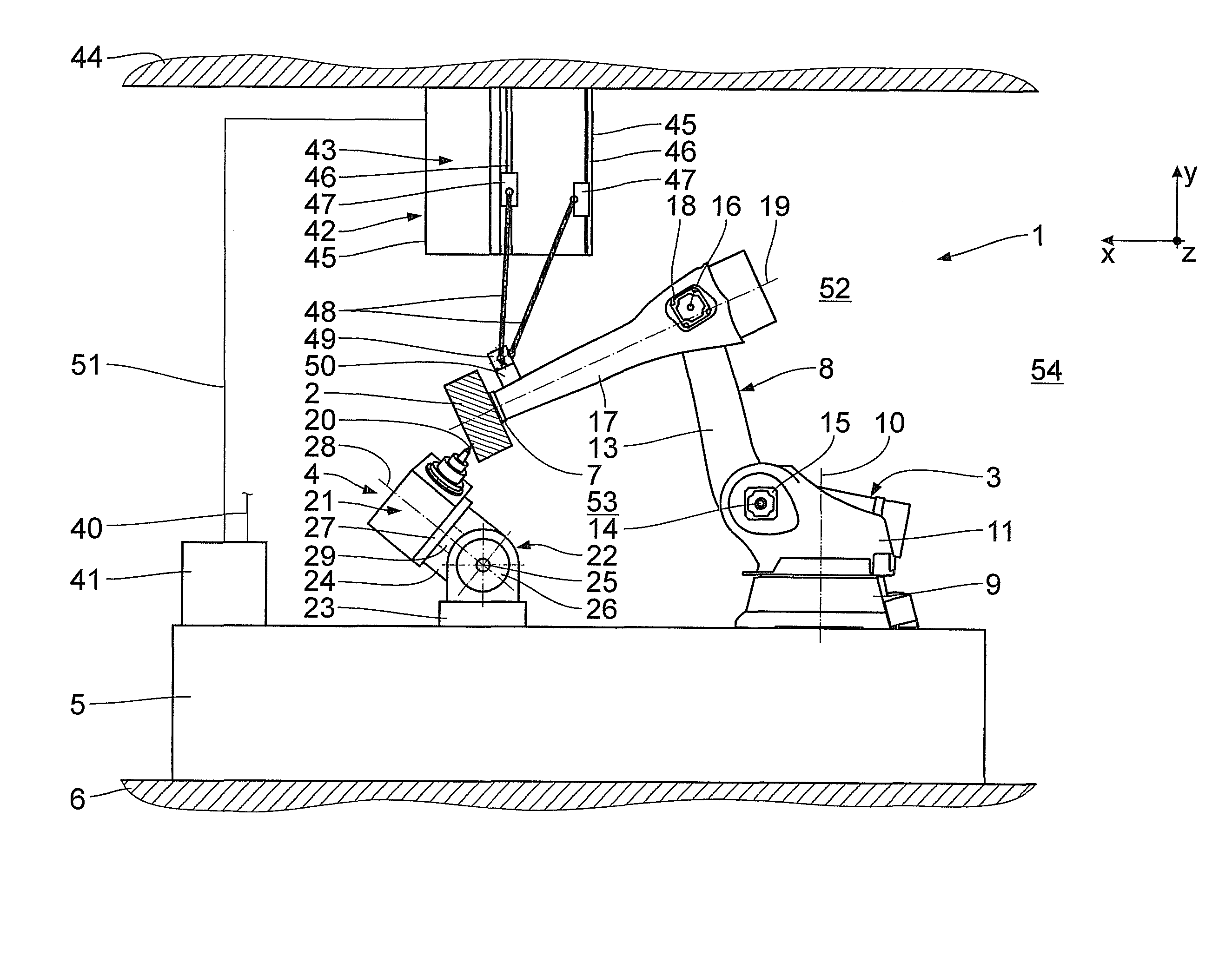
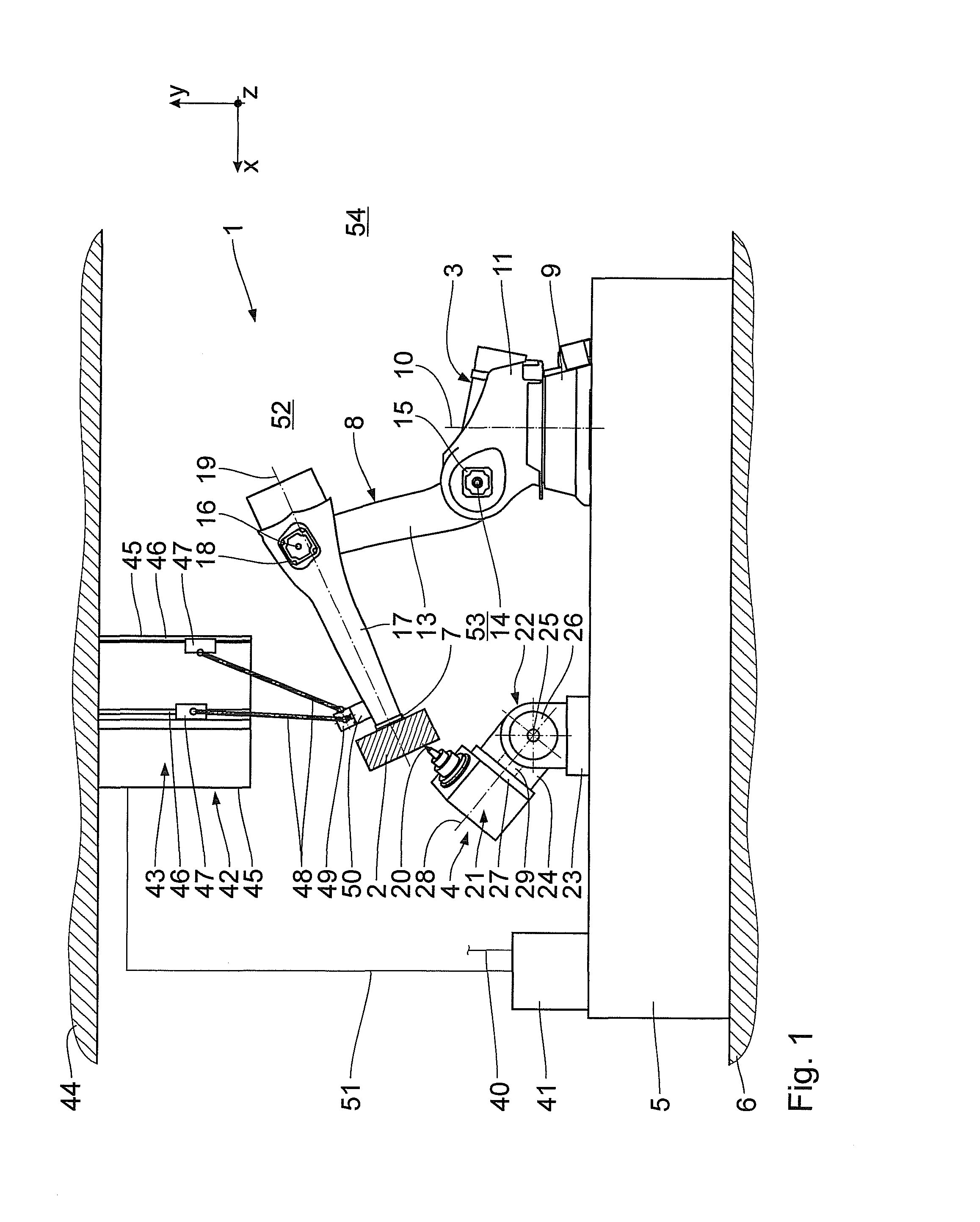
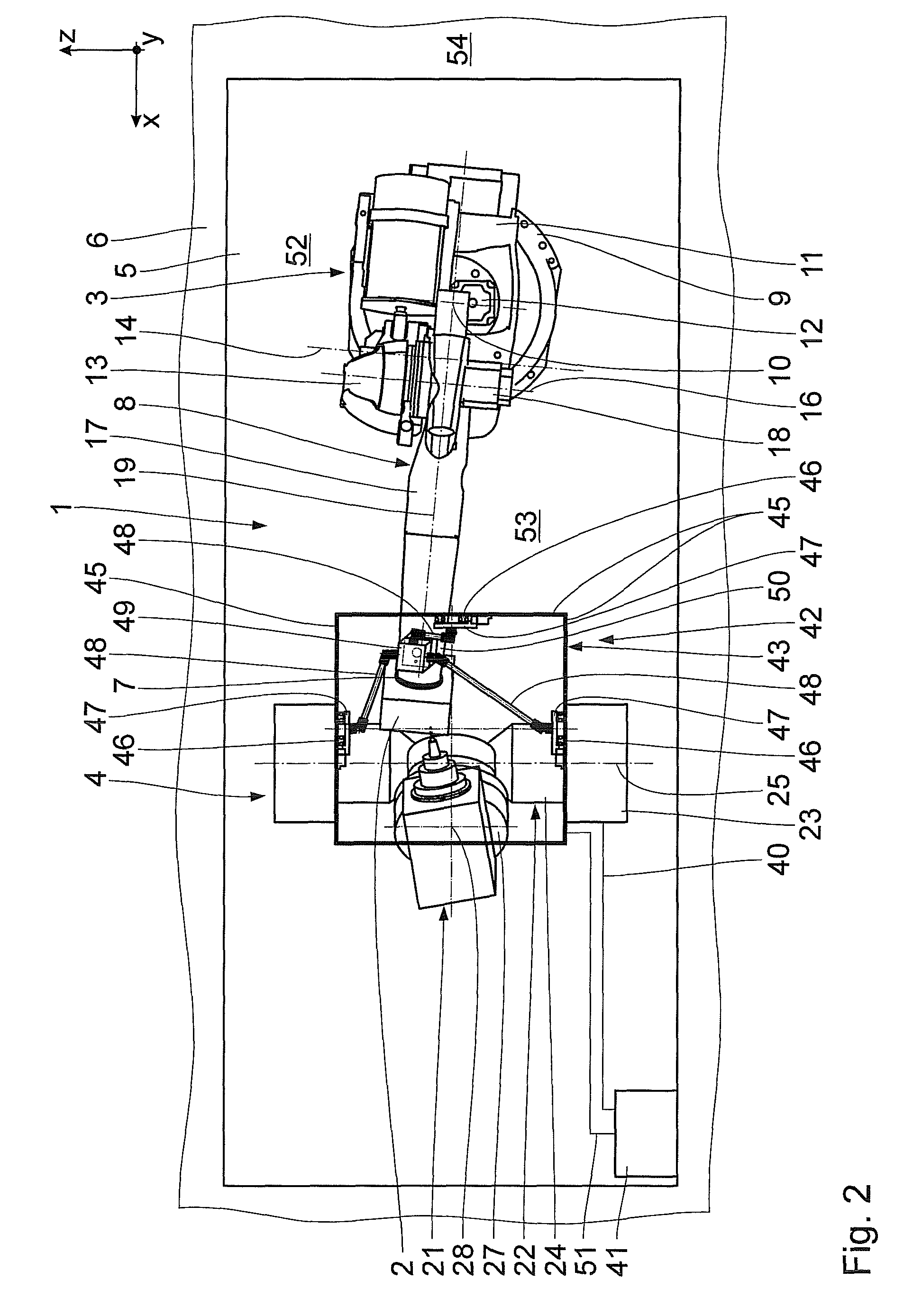
[0036]The following is a description, with reference to FIGS. 1 to 4, of the invention. A machining installation 1 for machining workpieces 2 comprises a workpiece positioning device 3 and a tool positioning device 4. The positioning devices 3, 4 are mounted on a common sub-frame 5 at a distance from each other. The sub-frame 5 is mounted on a base plate 6. Alternatively, the positioning devices 3, 4 may be mounted directly on the base plate 6.

[0037]The workpiece positioning device 3 is used for positioning the workpieces 2 to be machined and is designed in the manner of an industrial robot. The workpiece positioning device 3 comprises a workpiece holder 7 for receiving and holding the workpieces 2, the workpiece holder 7 being pivotably arranged on a base frame 9 via a workpiece holder pivot unit 8. The base frame 9 is mounted on the sub-frame 5. For pivoting the workpiece holder 7 about a vertical first workpiece holder pivot axis 10, the workpiece holder pivot unit 8 comprises a ...

third embodiment

[0073]In contrast to the third embodiment, the support frame 57c is in the shape of a U and formed in one piece with the second base frame 23b. The ends of the horizontal girder 59c are mounted to the vertical girders 58c. The position measuring unit 42c is a mechanical measuring kinematics in the shape of a joint arm. The joint arm comprises several rigid arm portions 83 which are interconnected in pairs via revolute joints 84 at their ends for rotation about in each case one horizontal rotary measuring axis 85. A first arm portion 83 at the end of the joint arm is mounted to the horizontal girder 59c for rotation about a vertical rotary measuring axis 85. A second arm portion 83 at another end of the joint arm is mounted to the first connection member49c for rotation about another rotary measuring axis 85. When the position measuring unit 42c is connected, this rotary measuring axis 85 is substantially parallel to the fourth workpiece holder pivot axis 19. The rotary measuring axe...


PUM

PropertyMeasurementUnit
Volumeaaaaaaaaaa
Volumeaaaaaaaaaa
Volumeaaaaaaaaaa

Abstract

A machining installation for workpieces comprises a workpiece positioning device comprising a workpiece holder pivot unit as well as a tool positioning device comprising a tool holder pivot unit. The workpiece holder pivot unit is designed such that a workpiece holder is pivotable about at least three and no more than four workpiece holder pivot axes. Moreover, the tool holder pivot unit is designed such that a tool holder is pivotable about no more than two tool holder pivot axes. The machining installation has a simple design and ensures flexible and accurate machining of workpieces.

Description

[0001]This application is a National Stage entry under 35 USC 371 of International Application PCT / EP2009 / 004746, filed Jul. 1, 2009, which claims foreign priority benefits under 35 USC 119 of German Application No. 102008031487.0, filed Jul. 3, 2008. The disclosure of each is expressly incorporated by reference herein in its entirety.BACKGROUND OF THE INVENTION[0002]1. Field of the Invention[0003]The invention relates to a machining installation for workpieces.[0004]2. Background Art[0005]A machining installation for workpieces designed as a machine tool is known from EP 1 155 771 A2. Several slides, which are displaceable along associated guide rails, are provided for positioning the workpiece holder and the tool spindle. The machine tool is loaded by means of a transport device which supplies the workpiece holders with the workpieces arranged thereon to one of the slides and picks them up again after machining. Although the described machine tool allows a high machining accuracy ...

Claims


Application Information

Patent Timeline
IPC IPC(8): B23C1/14B26D7/00B26D5/08G06F19/00B23Q3/155B23Q3/157B23Q11/00B24B5/00B24B9/00B23Q16/00B24B7/00B24B41/00B23D7/08B24B47/02
CPCB25J9/047B23Q7/04B25J13/088B23Q7/047Y10T83/8867Y10T83/889Y10T408/91Y10T409/305656Y10T409/305824Y10T409/306104Y10T409/307672Y10T409/308512Y10T409/309016Y10T409/309576Y10T483/15Y10T483/171Y10T483/1764Y10T483/1767Y10T483/1781Y10T483/1836
Inventor MEIDAR, MOSHE ISRAELHORN, WOLFGANGSCHMALZRIED, SIEGFRIEDHAUS, WALDEMAR
Owner MAG IAS
Why Eureka
Try Eureka