Liquid ejecting head and liquid ejecting apparatus

a liquid ejector and liquid ejector technology, applied in printing and other directions, can solve the problems of easy dislocation of the wall, loss of pressure, and amount of ink droplets, and achieve the effect of suppressing crosstalk

Active Publication Date: 2014-04-15
SEIKO EPSON CORP
View PDF8 Cites 3 Cited by
  • Summary
  • Abstract
  • Description
  • Claims
  • Application Information

AI Technical Summary

Benefits of technology

[0010]An advantage of some aspects of the invention is to provide a liquid ejecting head and a liquid ejecting apparatus capable of suppressing crosstalk when the liquid is ejected.
[0012]In the aspect, when the width of the adhesive in the arrangement direction of the pressure chambers in a state where the adhesive is flowed out from between a lower end portion of the partition wall and the bottom member to the pressure chamber side and then is solidified in a corner portion which is defined by the partition wall and the bottom member is L, the following expression is satisfied, 0.05≦L / W≦0.3. Accordingly, the bonding strength between the lower end portion of the partition wall and the bottom member is increased while preventing defects due to the outflow of the adhesive, that is, the defects that the adhesive regulates the operation of the pressure generation unit or the like. Thus, when the pressure change is generated inside the pressure chamber by driving the pressure generation unit to eject the liquid from the nozzle, the displacement of the partition wall is suppressed. Accordingly, when the liquid is ejected, the loss of the pressure is reduced and the crosstalk between adjacent nozzles is suppressed. In other words, the variation in the ejection characteristics (the amount and the flying speed of the liquid ejected from the nozzle) is suppressed.
[0014]In the aspect, the strength of the partition wall itself is increased while sufficiently securing the ejection amount of the liquid. Accordingly, the crosstalk is further reliably suppressed.
[0017]According to the configuration, the swelling rate of the adhesive is 10% or less when the adhesive is immersed in the liquid so that the swelling of the adhesive is suppressed and decrease of the bonding strength between the lower end portion of the partition wall and the bottom member is further suppressed. Accordingly, it contributes to the suppression of the crosstalk described above.
[0019]According to the configuration, since the viscosity of the adhesive in a case of the adhesive blended with silica is increased compared to the case of the adhesive not blended with silica, the defects due to the outflow of the adhesive can be further reliably suppressed.

Problems solved by technology

Thus, there are concerns that when the pressure change is generated inside the pressure chamber while the ink is ejected from the nozzle, crosstalk may be generated that the partition wall is easily displaced by the pressure, loss of the pressure is as much generated, and ejection characteristics of the ink droplet such as decrease of flying speed of the ink droplet, decrease of the amount of the ink droplet, and the like are changed.
The organic solvent-based ink is likely to cause swelling of the adhesive compared to the water-based ink.
In ejecting the ink having the compressibility greater than that of the water described above, there is a problem that deterioration of the crosstalk described above is further remarkable.
Thus, the partition wall is easily displaced (deformed) by the adjacent pressure chambers, and, as a result, the crosstalk is deteriorated.
In addition, the problems described above exist in the ink jet type recording apparatus having the recording head ejecting the ink and also exist in another liquid ejecting head and another liquid ejecting apparatus in which the liquid is ejected from the nozzle by driving the pressure generation unit and by generating the pressure change in the liquid inside the pressure chamber.

Method used


Image

  • Liquid ejecting head and liquid ejecting apparatus
  • Liquid ejecting head and liquid ejecting apparatus
  • Liquid ejecting head and liquid ejecting apparatus

Examples


Embodiment Construction

[0028]Hereinafter, embodiments of the invention will be described with reference to the accompanying drawings. In addition, in the embodiments described below, a variety of limitations are given as preferred specific examples of the invention, however, the range of the invention is not limited to the embodiments unless there is no description with a specific intention of limiting the invention. Furthermore, in the following description, an ink jet type recording apparatus (hereinafter, referred to as a printer 1) which has a recording head 2 that is a type of a liquid ejecting head is exemplified as the liquid ejecting apparatus of the invention.

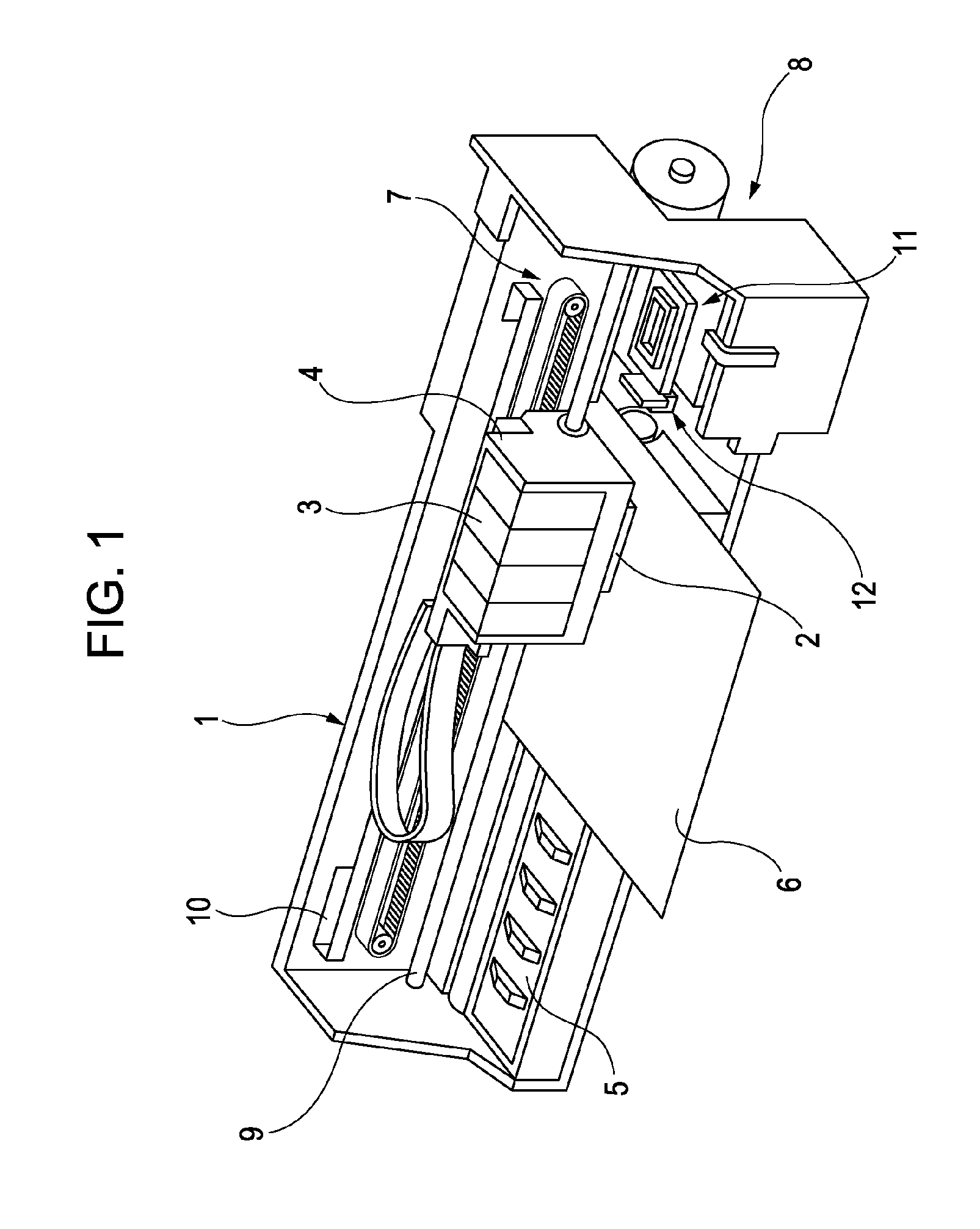
[0029]FIG. 1 is a perspective view illustrating a configuration of a printer 1. The printer 1 includes a carriage 4 in which the recording head 2 is installed and an ink cartridge 3 that is a type of a liquid supply source is detachably installed, a platen 5 which is disposed in the lower side of the recording head 2 when a recording operati...


PUM


Abstract

A liquid ejecting head includes a nozzle; a pressure chamber communicating with the nozzle; a pressure chamber substrate having pressure chambers defined by partition walls; a pressure generator generating pressure change in liquid inside the pressure chamber; and a bottom joined to the pressure chamber substrate by adhesive; and an organic solvent-based ink ejected from the nozzle by driving a piezoelectric element and generating the pressure change in the pressure chamber, and when a width of the pressure chamber in an arrangement direction of the pressure chambers is W and a width of the adhesive in the arrangement direction of the pressure chambers in a state where the adhesive has flowed out from between a lower end portion of the partition wall and the bottom to the pressure chamber side and is then solidified is L, the following expression is satisfied, 0.05≦L / W≦0.3.

Description

[0001]The entire disclosure of Japanese Patent Application Nos. 2012-039533, filed Feb. 27, 2012 and 2012-041933, filed Feb. 28, 2012 are expressly incorporated by reference herein.BACKGROUND[0002]1. Technical Field[0003]The present invention relates to a liquid ejecting head installed in a liquid ejecting apparatus such as an ink jet type recording apparatus and a liquid ejecting apparatus having the liquid ejecting head, and more particularly, to a liquid ejecting head which ejects a liquid from a nozzle by generating a pressure change in the liquid inside a pressure chamber by deforming an operation surface configuring a portion of the pressure chamber communicating with the nozzle and a liquid ejecting apparatus.[0004]2. Related Art[0005]A liquid ejecting apparatus includes a liquid ejecting head capable of ejecting a liquid from a nozzle as a liquid droplet and is an apparatus which ejects various types of liquids from the liquid ejecting head. As a typical example of the liqui...

Claims


Application Information

Patent Timeline
Patent Type & Authority Patents(United States)
IPC IPC(8): B41J2/045
CPCB41J2/14233B41J2/1623B41J2/161B41J2/14201
Inventor OZAWA, KINYATSUCHIHASHI, RYOSUKEMAKITA, SHUSHI
Owner SEIKO EPSON CORP
Why Eureka
Try Eureka