Eureka AIR delivers breakthrough ideas for toughest innovation challenges, trusted by R&D personnel around the world.

Nozzle and fluidic circuit adapted for use with cold fluids, viscous fluids or fluids under light pressure

a fluidic circuit and nozzle technology, applied in the direction of burners, combustion types, combustion processes, etc., can solve the problems of inability to perform circuits, insatiable feedback circuits, etc., and achieve the effect of reducing the pressure needed to produce spray, improving cp, and enhancing jet expansion

Active Publication Date: 2014-04-22
DLHBOWLES INC
View PDF5 Cites 22 Cited by
  • Summary
  • Abstract
  • Description
  • Claims
  • Application Information

AI Technical Summary

Benefits of technology

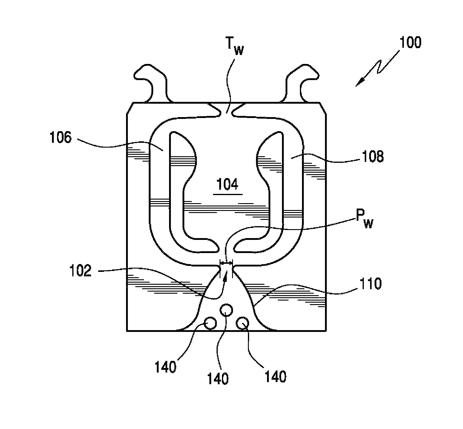
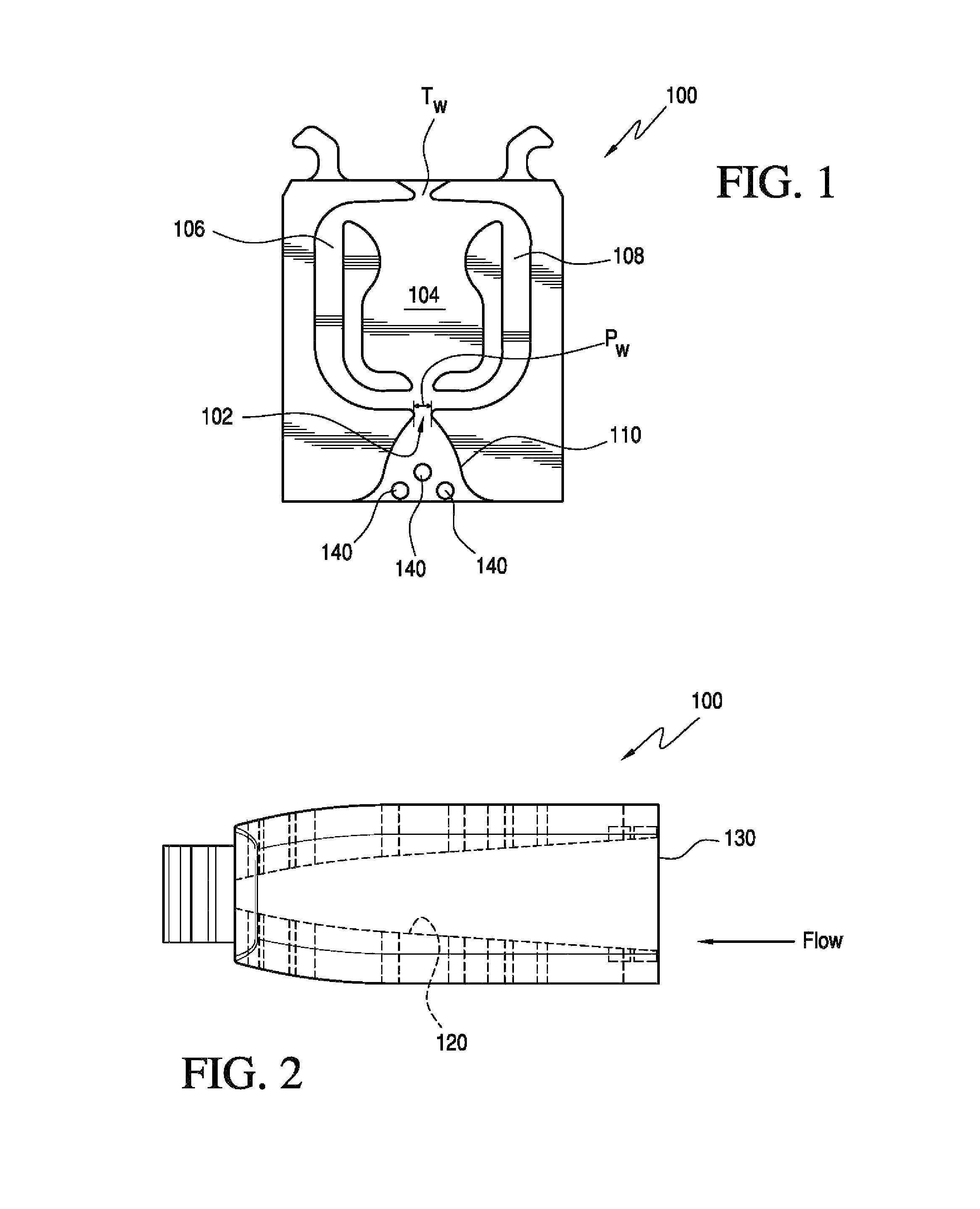
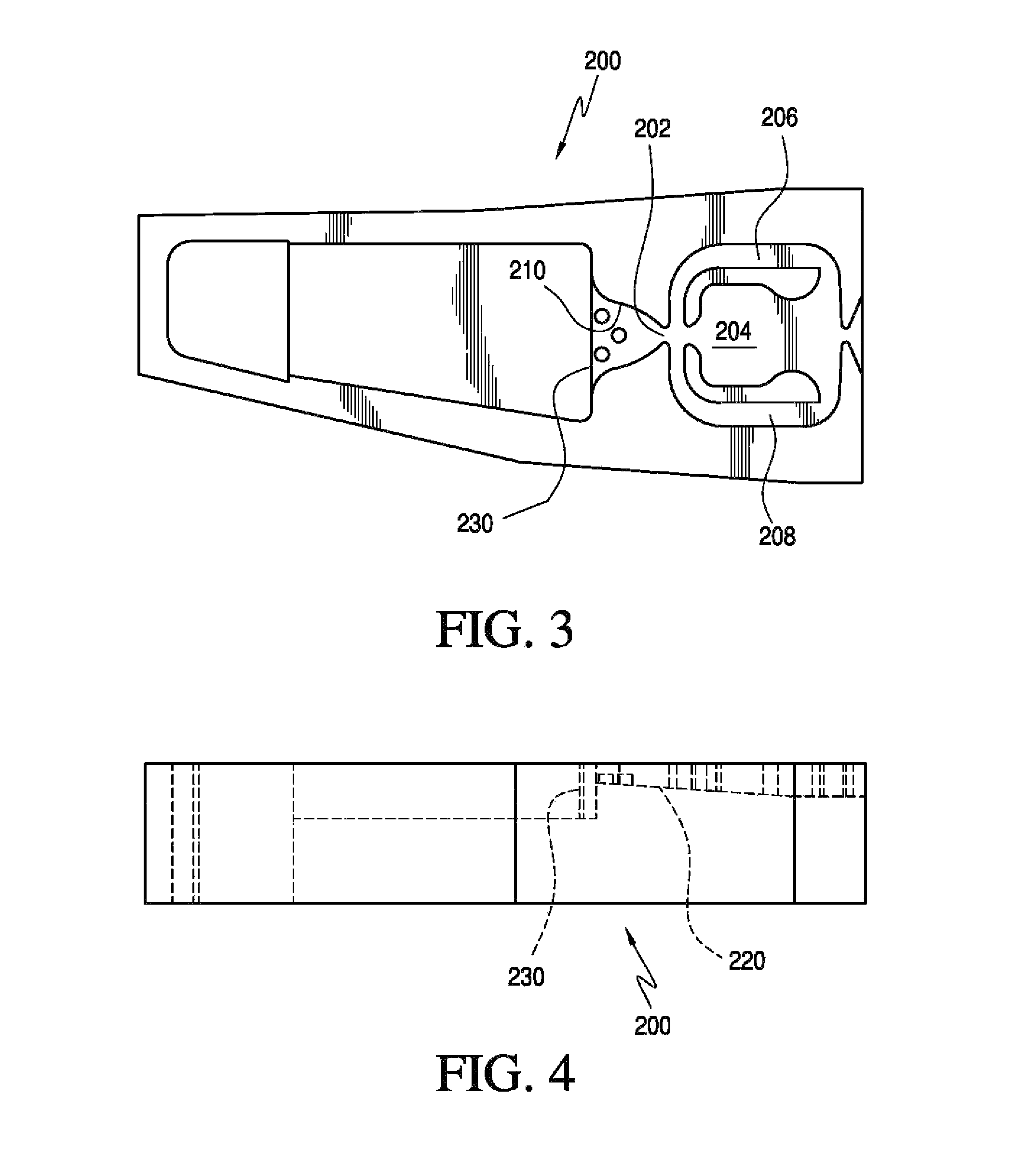
[0014]The nozzle system of the present invention is adapted for use with cold or viscous fluids and includes a fluidic oscillator having a power nozzle and an oscillation chamber coupled to the power nozzle for issuing a jet of fluid into the oscillation chamber and an outlet aperture spraying a jet of fluid into ambient space. The oscillator's walls define an oscillation inducing interaction region causing the jet of fluid to rhythmically sweep back and forth between the sidewalls in the oscillation chamber. The oscillation inducing interaction region defines an outlet throat width which is adapted to work with the power nozzle's width and an a bell-shaped feed that spreads the fluid jet as it leaves the power nozzle, so that the interaction region and feedback channels are quickly filled with fluid at a low pressure and the fluidic oscillator is activated.
[0020]Recr′ can be reduced by introducing geometrical features in the fluidic circuit, which is done with knowledge of fluid mechanics and fluidics and with experimentation. This application describes new geometrical features added to the existing feedback circuit to significantly improve its CP. The improved fluidic is therefore identified as the CP feedback circuit.
[0022]Second, the CP feedback circuit includes a downward taper on the floor beginning from the leading edge of the feed. In developmental prototypes, this taper was designed to begin at the leading edge of the insert. The taper was chosen to be in the range of 3 deg-8 deg. Thus, the entire circuit is a diverging channel and promotes expansion of the jet along the side. The jet can then expand in all directions leading to quicker diffusion in the interaction region and formation of vortices, which activate the fluidic.
[0024]Fourth, short posts were introduced in the feed area. These posts act to enhance the jet expansion from the power nozzle and can also be a filtering element.
[0025]The effect of all these features, when combined, is to improve the CP significantly. The pressure needed to produce a spray has been reduced by 10-12 psi (approx. 50%) with a liquid of viscosity 25 cP.

Problems solved by technology

The existing feedback circuits are not satisfactory for some applications, where CP requirements are high and the existing feedback circuits cannot perform.

Method used


Image

  • Nozzle and fluidic circuit adapted for use with cold fluids, viscous fluids or fluids under light pressure
  • Nozzle and fluidic circuit adapted for use with cold fluids, viscous fluids or fluids under light pressure
  • Nozzle and fluidic circuit adapted for use with cold fluids, viscous fluids or fluids under light pressure

Examples


Embodiment Construction

[0032]Two embodiments of improved Cold Performance nozzle assemblies are illustrated in FIGS. 1-4.

[0033]As noted above, cold performance is the ability of a nozzle to spray effectively at cold temperatures (e.g. 0° F.). The liquid used at such temperatures can be an alcohol mix with water that have low freezing points. Thus, the viscosity of the liquid is high (e.g. 25 cP; water viscosity at RT is 1 cP). In essence, CP is the ability of a nozzle to reliably generate oscillation and effectively spray thick or viscous liquids into a desired spray or fan pattern, while pressurized with commercially reasonable fluid pressures.

[0034]CP is desirable for certain automotive windshield and headlamp washer nozzles. CP feedback circuits of the present invention are designed for use in the applicant's X-factor 3D spray nozzle for headlamp cleaning. In addition, it can also be used for windshield washer nozzles.

[0035]The applications where CP requirements are high include X-factor (3D spray patt...


PUM


Abstract

A fluid spraying or nozzle system adapted for use with cold fluids, viscous fluids or fluids under light pressure includes a fluidic oscillator having a power nozzle and an oscillation chamber coupled to the power nozzle for issuing a jet of fluid into the oscillation chamber and an outlet aperture spraying a jet of fluid into ambient space. The oscillator's walls define an oscillation inducing interaction region causing the jet of fluid to rhythmically sweep back and forth between the sidewalls in the oscillation chamber. The oscillation inducing interaction region defines an outlet throat width which is adapted to work with the power nozzle's width and an a bell-shaped feed that spreads the fluid jet as it leaves the power nozzle, so that the interaction region and feedback channels are quickly filled with fluid at a low pressure and the fluidic oscillator is activated to generate a desired fan pattern of fluid spray.

Description

PRIORITY CLAIM AND REFERENCE TO RELATED APPLICATION[0001]This application claims priority to related, commonly owned U.S. provisional patent application No. 61 / 071,778, filed May 16, 2008, the entire disclosure of which is incorporated herein by reference.BACKGROUND OF THE INVENTION[0002]1. Field of the Invention[0003]The present invention relates to nozzles and fluidic circuits for generating a controlled spray pattern.[0004]2. Discussion of the Prior Art[0005]Fluidic inserts or oscillators are well known for their ability to provide a wide range of distinctive liquid sprays. The distinctiveness of these sprays is due to the fact that they oscillate, as compared to the relatively steady state flows or streams emitted from standard spray nozzles.[0006]For ease of construction, fluidic oscillators or inserts are generally manufactured as thin, rectangular members that are molded or fabricated from plastic so as to have specially-designed liquid flow channels fabricated into either th...

Claims


Application Information

Patent Timeline
Patent Type & Authority Patents(United States)
IPC IPC(8): B05B1/08
CPCB05B1/08
Inventor GOPALAN, SHRIDAR
Owner DLHBOWLES INC
Why Eureka
Eureka Blog
Learn More