
Simulated head mounted display system and method

a display system and head mounted technology, applied in the field of simulator image display systems, can solve problems such as eye strain, unsatisfactory double-image effect, and perception problems, and achieve the effect of reducing the difficulty of visual processing, reducing and improving the effect of visual processing

Inactive Publication Date: 2014-04-22
L 3 COMM CORP
View PDF11 Cites 95 Cited by
  • Summary
  • Abstract
  • Description
  • Claims
  • Application Information

AI Technical Summary

Benefits of technology

This patent is about a head-mounted display system that allows users to experience out-the-window imagery in a simulator. The system includes a display screen and a simulation computer system that generates real-time video based on virtual objects and scenarios. The system also includes a tracking system that detects the user's position and generates a virtual representation of the user's eye. The virtual image is then combined with the real-time video to create a seamless, immersive experience for the user. The technical effect of this invention is to provide a more realistic and immersive training experience for users of simulators.

Problems solved by technology

The closeness of the projected images produces some perceptual issues.
This double-image effect is unrealistic and undesirable in a simulator, and presents a significant problem in training using a binocular HMD in combination with a projected OTW scene.
The user may be able to shift back and forth between the OTW and the HMD images, but that creates eye strain or else increased visual cognition time for the user.
The relative parallax effect of viewing the screen arrangement from one eye location relative to the other may be quite complicated as a result.
Moreover, the HMD imagery may be more complex than just character-based symbology, and may be a detailed field of view, such as a Forward Looking Infra-Red (FLIR) image.
Use of a standard HMD imagery system in such a simulation would make the quality of the virtual training unrealistic and well below the quality of display found in the real vehicle, reducing the value of such training.
However, the monocular HMD simulation is not the same experience as the binocular HMD real vehicle operation.
There are no systems in the prior art that provide for an adequate operation of a binocular HMD in a simulator where out-the-window imagery is displayed on screens or similar display apparatus.

Method used


Image

  • Simulated head mounted display system and method
  • Simulated head mounted display system and method
  • Simulated head mounted display system and method

Examples


Embodiment Construction

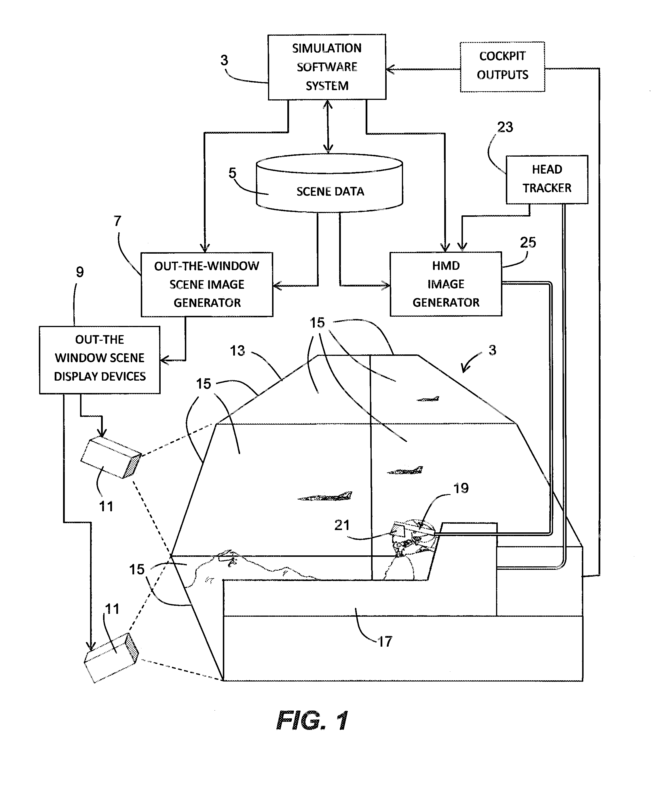
[0035]Referring to FIG. 1, a simulator station 3 is shown. The simulator is a computerized real-time system that interacts with a user, i.e., a trainee pilot when the simulated vehicle is an aircraft.

[0036]As is well known in the simulation arts, the simulation software system 3 is a computer system or set of computers connected to operate contemporaneously and administer the simulation by executing stored software, and it administers the entire operation of the simulation, including the operation of the simulated vehicle, all input / output from the simulator, including operator cockpit controls, and also to displays that are shown to the user. The simulator includes a computer system with processor, input / output circuitry, and data storage circuitry and devices supported by a stored operating system and attendant stored software.

[0037]The simulation software system 3 includes a computer-accessible data storage device 5 storing scene data that defines the virtual environment in which...


PUM


Abstract

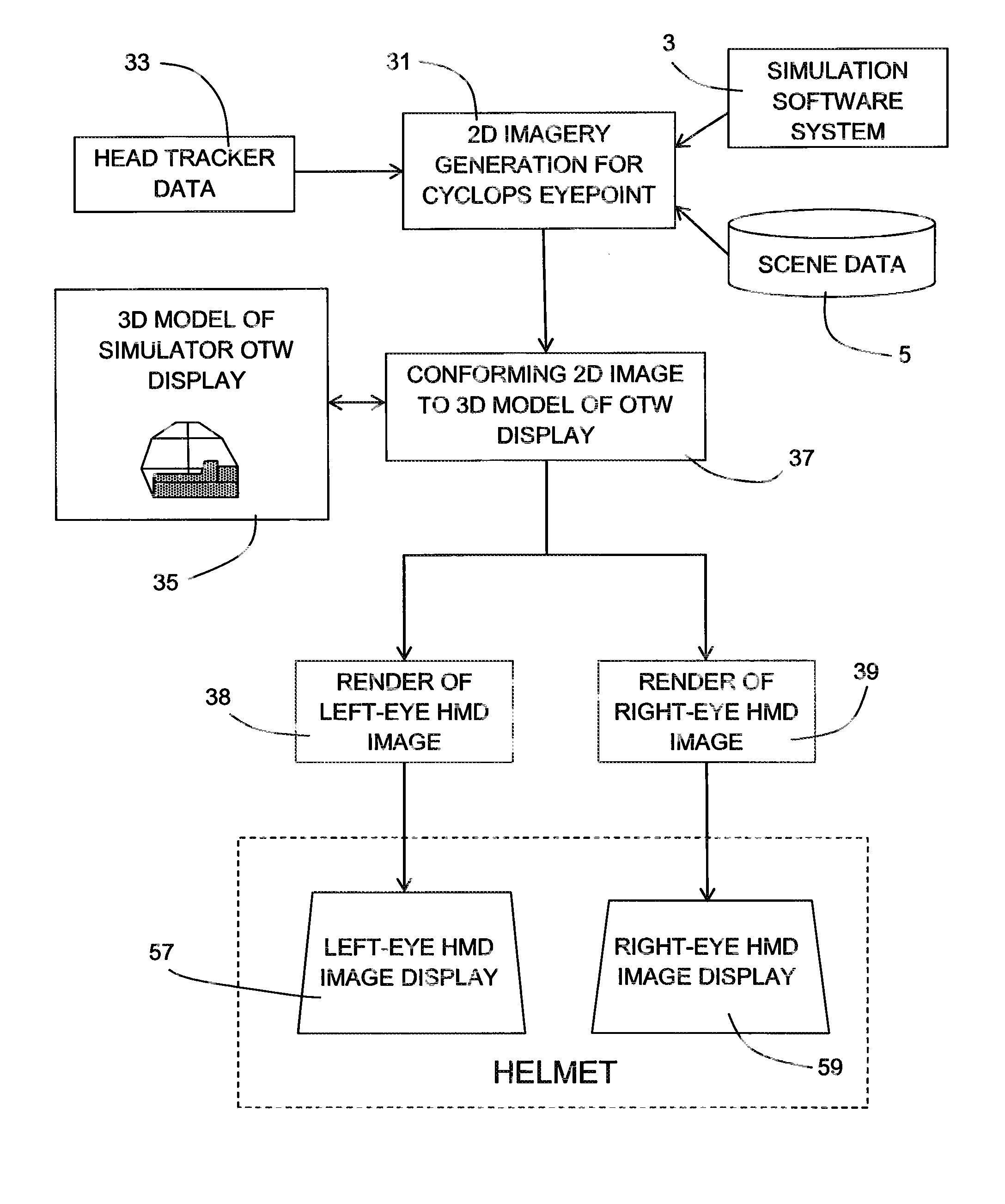
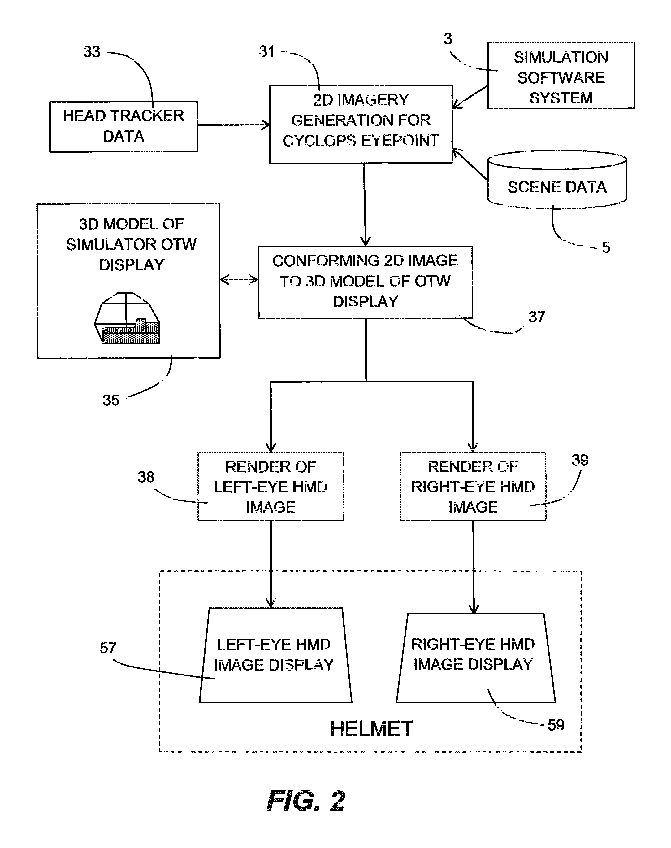
To overcome problems with vergence, a binocular head mounted display (HMD) is used in a simulator in which an out-the-window scene is displayed in real time on a screen arrangement. Imagery for the left and right eyes of the HMD is derived by generating a starting HMD image for a Cyclops viewpoint between the user's eves, and then rendering respective views for each eve from the position of the eye in a virtual 3D model of the screen arrangement, wherein the starting HMD image is frustum projected against the screen arrangement of the 3D model.

Description

FIELD OF THE INVENTION[0001]The present invention relates to simulator image display systems, more particularly to simulators in which a head-mounted display is used to display symbology or imagery to the user.BACKGROUND OF THE INVENTION[0002]Military aircraft and other vehicles are frequently equipped with head-mounted displays (HMDs) through which the operator of the vehicle can see objects in the environment. The HMD displays imagery, especially tactical or other symbology, superimposed over objects in the real world seen from the vehicle to which the information in the imagery relates.[0003]While HMDs are often monocular, the industry is beginning to more frequently employ binocular HMDs. i.e., HMDs with two separate eye displays, usually implemented with a helmet visor that has a semi-reflective mirror over each eye of the operator. Each eye of the operator can see the real world outside the canopy or windshield of the vehicle, and can also see an HMD virtual image reflected in...

Claims


Application Information

Patent Timeline
Patent Type & Authority Patents(United States)
IPC IPC(8): G09B19/16G09G5/00H04N9/47H04N13/363
CPCG06F3/011H04N13/0459H04N13/0484G06F3/012H04N13/004H04N13/044H04N13/344H04N13/156H04N13/363H04N13/383
Inventor TURNER, JAMES, A.
Owner L 3 COMM CORP
Learn More