

Tool for predicting capacity demands on an electronic system
a technology for electronic systems and tools, applied in mechanical power/torque control, two-way working systems, ratio control, etc., can solve problems such as system inoperability, unnecessary hardware costs, and customer dissatisfaction
- Summary
- Abstract
- Description
- Claims
- Application Information
AI Technical Summary
Benefits of technology
Problems solved by technology
Method used
Image

Examples
Embodiment Construction
)
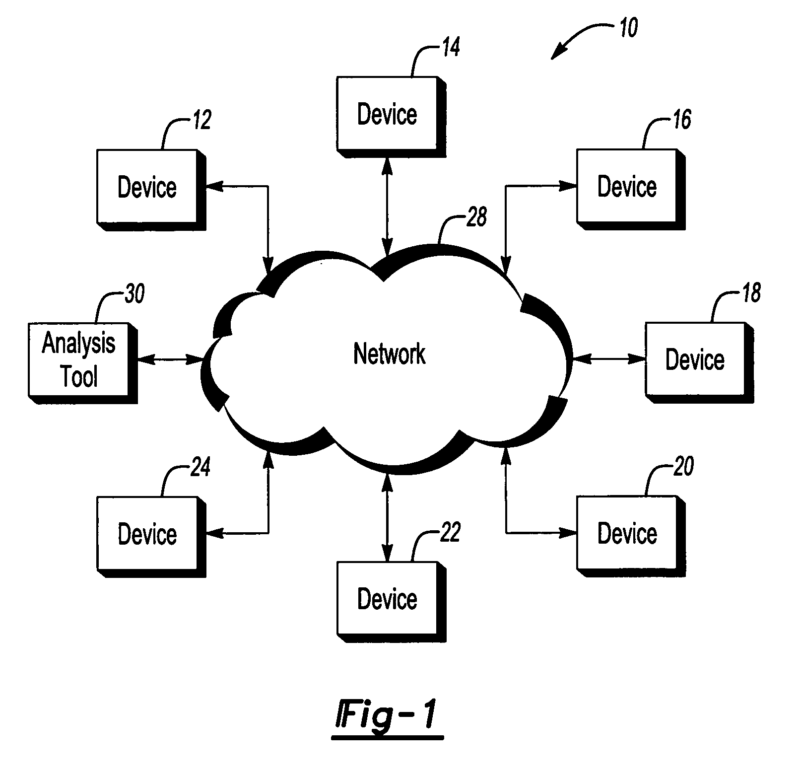
[0009]FIG. 1 illustrates a system 10 in accordance with one non-limiting aspect of the present invention. The system 10 may relate to any number of environments where signals are transmitted between a plurality of electronic devices 12-24. For exemplary purposes, the present invention is described with respect to the system 10 being configured to support signal communications associated with cable operations. Of course, the present invention is not intended to be so limited and contemplates its application in any number of environments.
[0010]With respect to the exemplary cable environment, one or more of the devices 12-24 may include or be associated with a system (headend) or other feature of a cable service provider to facilitate signal communications between other devices. It may include a memory (not shown), user interface (not shown), and other features to control, program, and execute the operation thereof. The devices 12-24 may include or be associated with any number of ele...
PUM
 Abstract
Description
Claims
Application Information