Battery protection structure for automobile

a protection structure and battery technology, applied in the direction of roofs, vehicle sub-unit features, electric propulsion mounting, etc., can solve the problems of increasing the mass and cost of the body, and difficulty in keeping the amount of deformation (deformation stroke) of the body's side portion

Active Publication Date: 2014-04-29
TOYOTA JIDOSHA KK
View PDF18 Cites 45 Cited by
  • Summary
  • Abstract
  • Description
  • Claims
  • Application Information

AI Technical Summary

Benefits of technology

[0008]The present invention provides a battery protection structure for an automobile that can protect a battery in a favorable manner from deformation of the body's side portion in a lateral collision, and can keep the mass and cost of the body from increasing.
[0010]In the above-mentioned configuration, the input member connects between the rocker that is placed in the side portion of the body, and the reinforcement that is placed more inward in the body width direction than the rocker. When a collision load directed inward in the body width direction is inputted to the rocker in a lateral collision, the input member inputs a part of the collision load to the midsection of the floor panel between the rocker and the reinforcement as a component directed upward of the body. The floor panel thus deforms toward the upper side of the body. As a result, the impact energy is dispersed, thereby reducing the amount of deformation (deformation stroke) of the body's side portion toward the inner side in the body width direction. Consequently, the battery that is placed more inward in the body width direction than the rocker and below the floor panel in the body can be protected from deformation of the body's side portion in a favorable manner. Moreover, the input member may simply be any member that guides deformation of the floor panel toward the upper side of the body. Thus, the input member can be constructed with light weight and at low cost. Therefore, it is possible to keep the mass and cost of the body from increasing.
[0012]In the above-mentioned configuration, the input member connects between the rocker that is placed in the side portion of the body, and the reinforcement that is placed more inward in the body width direction than the rocker. This input member is joined to the floor panel. When a collision load directed inward in the body width direction is inputted to the rocker in a lateral collision, the input member flexes in its midsection in the body width direction so as to rise (elevate) toward the upper side of the body. The floor panel thus deforms toward the upper side of the body. As a result, the impact energy is dispersed, thereby reducing the amount of deformation (deformation stroke) of the body's side portion toward the inner side in the body width direction. Consequently, the battery that is placed more inward in the body width direction than the rocker and below the floor panel in the body can be protected from deformation of the body's side portion in a favorable manner. Moreover, the input member may simply be any member that guides deformation of the floor panel toward the upper side of the body. Thus, the input member can be constructed with light weight and at low cost. Therefore, it is possible to keep the mass and cost of the body from increasing.
[0014]In the above-mentioned configuration, the input member and the frame of the vehicle seat overlap each other in plan view. Thus, when the floor panel is deformed toward the upper side of the body by the input member, the floor panel can be brought into contact with the frame of the vehicle seat. Therefore, the amount of impact energy absorption can be increased, thereby reducing the amount of deformation of the body's side portion toward the inner side in the body width direction.
[0016]In the above-mentioned configuration, when a collision load directed inward in the body width direction is inputted to the rocker in a lateral collision, a part of the collision load is transmitted to the inner end in the body width direction of the inside reinforcing member via the slope portion of the outside reinforcing member. The slope portion slopes so as to elevate as the slope portion extends inward in the body width direction. Therefore, the load transmitted to the inside reinforcing member via the slope portion includes a component that is directed inward in the body width direction, and a component that is directed upward of the body. The component directed inward in the body width direction is supported by the compressive strength of the inside reinforcing member. Thus, a rotation moment is exerted on the inside reinforcing member by the component directed upward of the body, with the reinforcement side end of the inside reinforcing member as a fulcrum. Thus, as the inside reinforcing member rotates toward the upper side of the body owing to the rotation moment, the input member flexes toward the upper side of the body at the fragile portion that is provided between the inside reinforcing member and the outside reinforcing member. Therefore, the area of the floor panel facing the fragile portion flexes toward the upper side of the body together with the input member, causing the floor panel to deform toward the upper side of the body with this flexing portion being situated at the top. Since the input member is divided into the outside reinforcing member and the inside reinforcing member, the strength, rigidity, and the like of the two reinforcing members can be set individually. Consequently, the deformation mode of the input member can be easily set.
[0018]In the above-mentioned configuration, the outside reinforcing member and the inside reinforcing member that are secured to the floor panel define a closed section as mentioned above. Therefore, it is possible to make the input member lightweight while securing the strength and rigidity required for the outside reinforcing member and the inside reinforcing member.

Problems solved by technology

With the floor structure mentioned above, in cases such as when a high capacity, large sized battery is required or when the width dimension of the vehicle is small, it is difficult to keep the amount of deformation (deformation stroke) of the body's side portion in a lateral collision to an extent that can avoid interference between the body's side portion and the battery.
However, such a configuration leads to an increase in the mass and cost of the body.

Method used


Image

  • Battery protection structure for automobile
  • Battery protection structure for automobile
  • Battery protection structure for automobile

Examples


Embodiment Construction

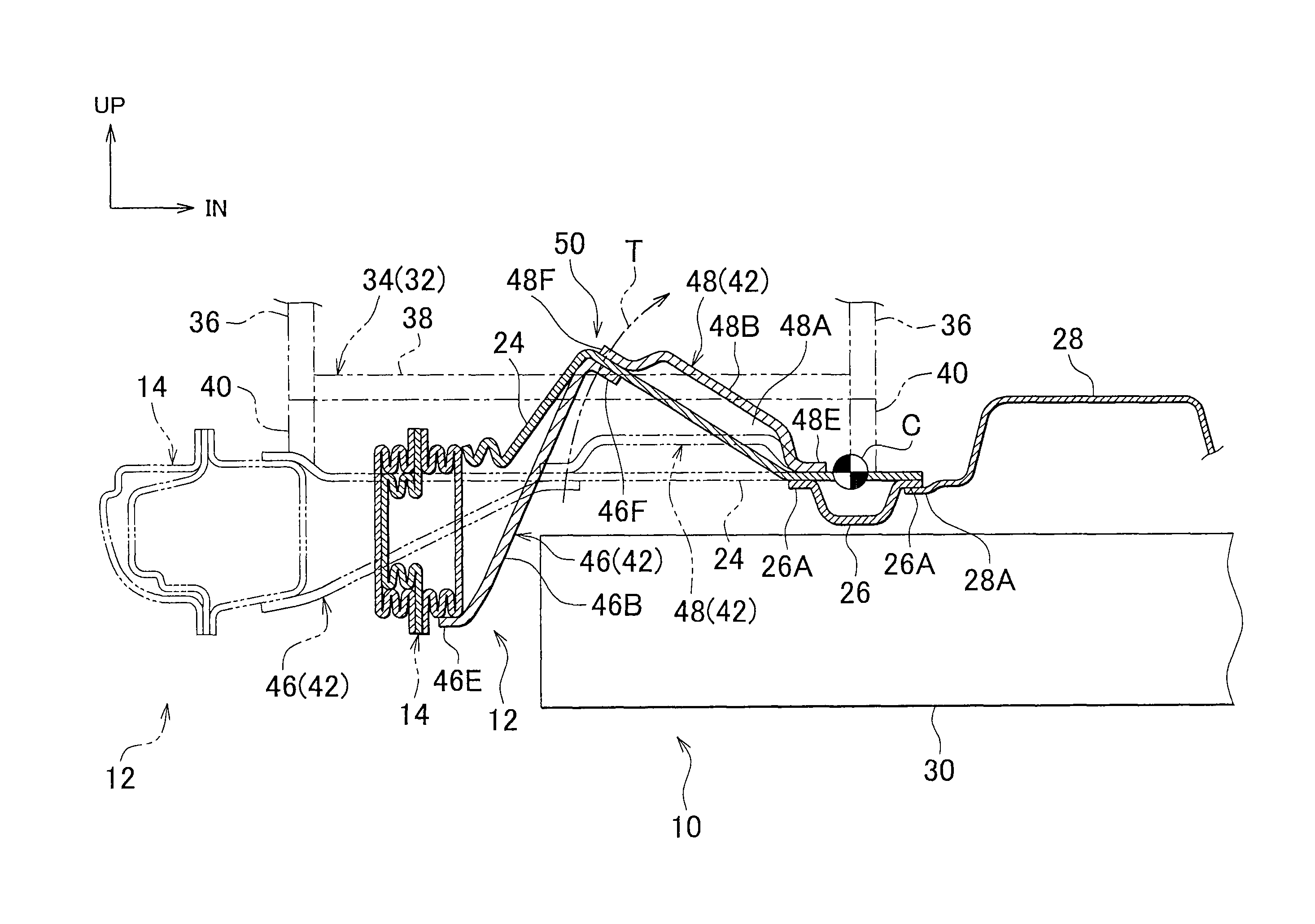
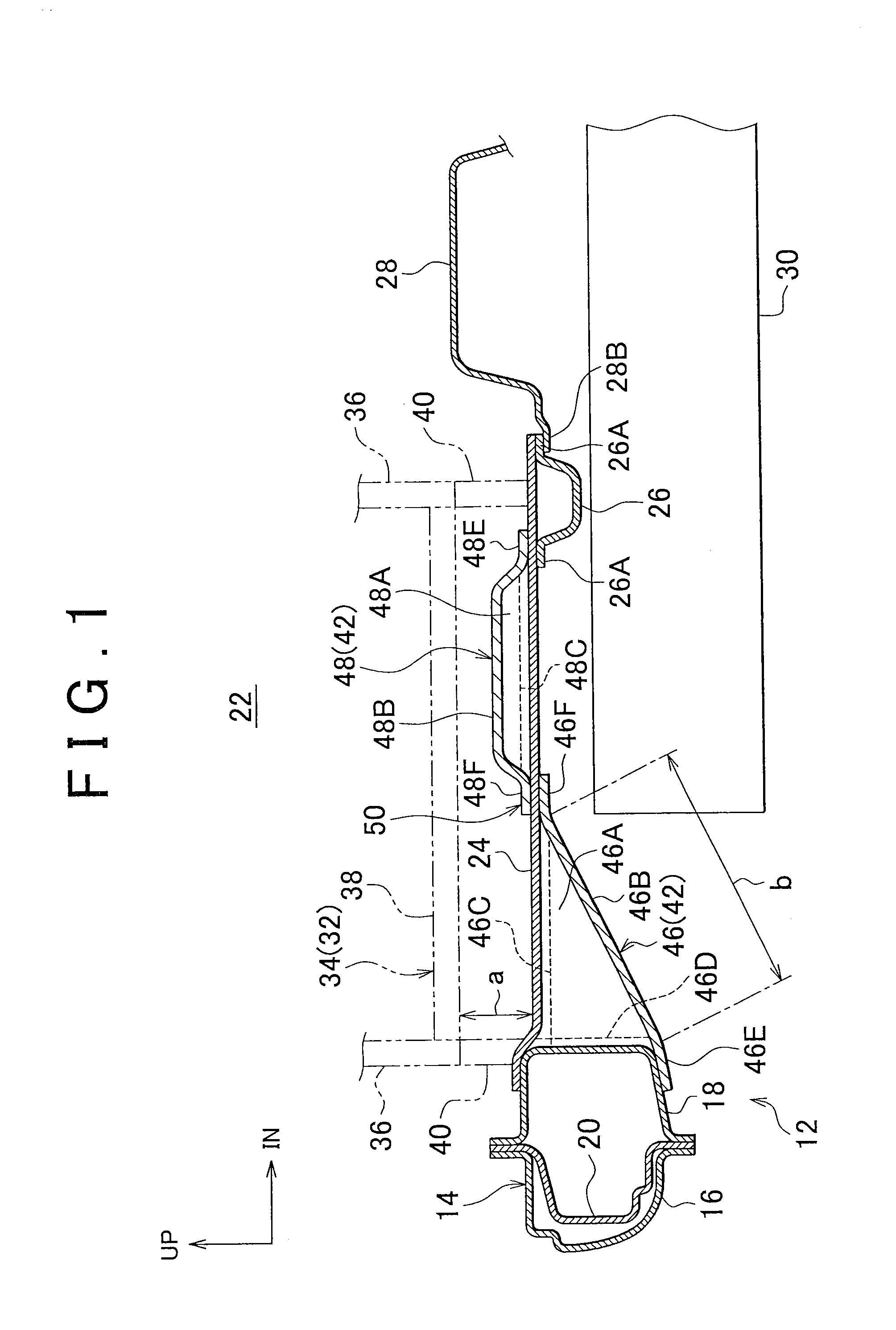
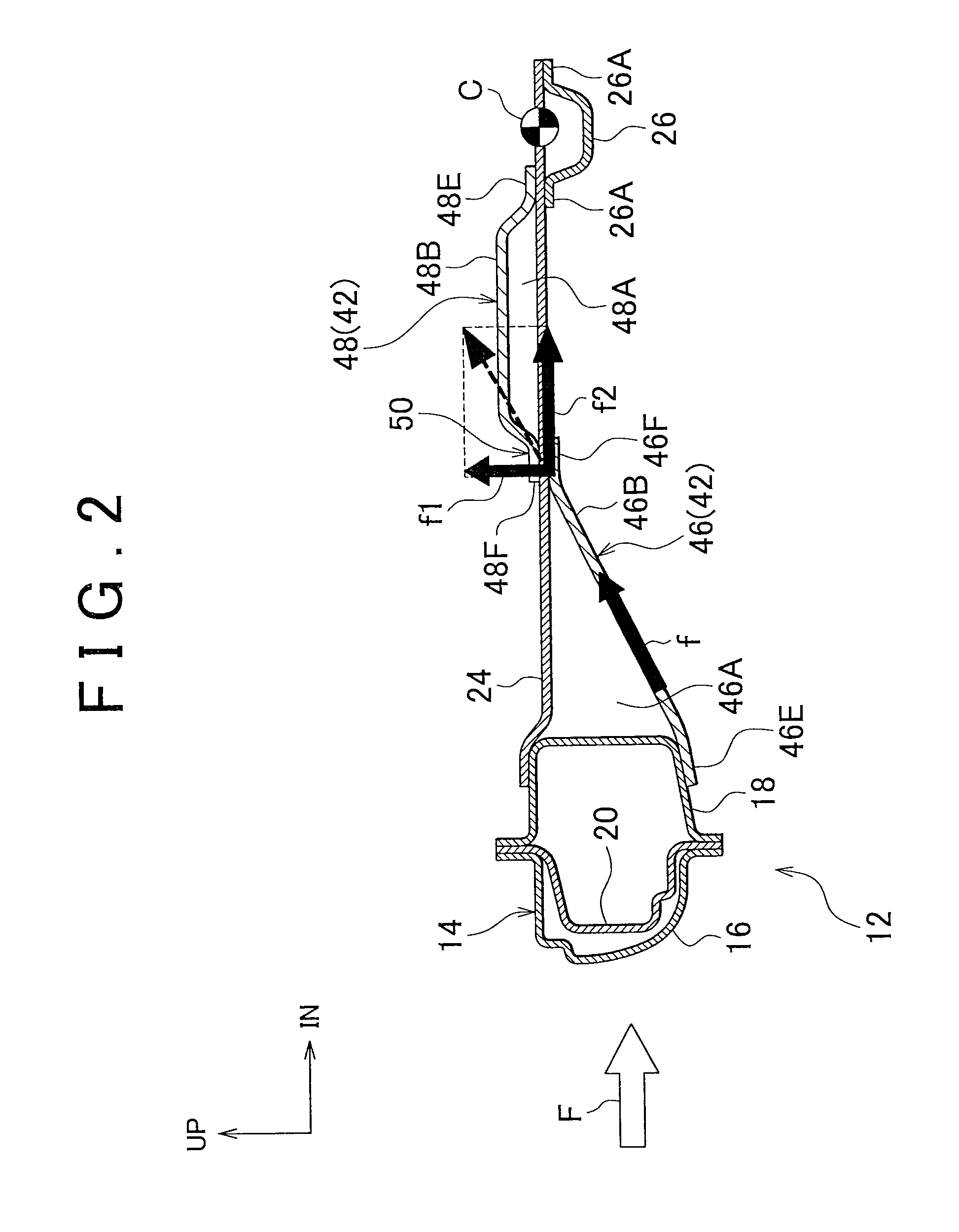
[0024]A battery protection structure for an automobile according to an embodiment of the invention is described below with reference to FIGS. 1 to 4. In FIGS. 1 to 4, the arrow UP indicates the upper side of the vehicle, and the arrow IN indicates the inner side in the vehicle width direction.

[0025]FIG. 1 is a vertical sectional view of a battery protection structure 10 for an automobile according to this embodiment as viewed from the body's front side. This automobile is, for example, an automobile installed with a battery 30 such as an electric automobile, a gasoline hybrid vehicle, or a fuel cell hybrid vehicle. The battery protection structure 10 for an automobile according to this embodiment is applied to such an automobile.

[0026]As illustrated in FIG. 1, a rocker 14 is arranged in a body's side portion 12 of the automobile. The rocker 14 is a body frame member with a closed sectional structure that extends along the front-to-rear direction of the body. The rocker 14 includes a...


PUM


Abstract

A battery protection structure for an automobile includes a rocker placed in a side portion of a body, a floor panel whose outer end in a body width direction is secured to the rocker, a reinforcement located more inward in the body width direction than the rocker, and secured to the floor panel, the reinforcement forming a part of a frame of the body, a battery located more inward in the body width direction than the rocker, and placed below the floor panel in the body, and an input member that connects between the rocker and the reinforcement, and configured to input, upon input of a collision load directed inward in the body width direction to the rocker, a part of the collision load to a midsection of the floor panel between the rocker and the reinforcement as a component directed upward of the body.

Description

INCORPORATION BY REFERENCE[0001]The disclosure of Japanese Patent Application No. 2011-163511 filed on Jul. 26, 2011 including the specification, drawings and abstract is incorporated herein by reference in its entirety.BACKGROUND OF THE INVENTION[0002]1. Field of the Invention[0003]The invention relates to a battery protection structure for protecting a battery placed below the floor panel in the body of an automobile, from deformation of the body's side portion in a lateral collision.[0004]2. Description of Related Art[0005]In the floor structure for an electric automobile disclosed in Japanese Patent Application Publication No. 7-156831 (JP 7-156831 A), a side member is mounted on the lower surface of the side portion of a floor panel. A battery frame installed with a battery is mounted on the side member. An outrigger is mounted between a side sill (rocker) provided at the side edge of the floor panel and the side member. The outrigger is provided with an extended portion that i...

Claims


Application Information

Patent Timeline
Patent Type & Authority Patents(United States)
IPC IPC(8): B62D21/02B62D21/15
CPCB62D21/157B60K1/04B60Y2306/01B62D25/2036B60K2001/0438
Inventor SAEKI, KOJI
Owner TOYOTA JIDOSHA KK
Why Eureka
Try Eureka