Invisible fence battery charger

a battery charger and invisible fence technology, applied in the field of new invisible fence battery chargers, can solve the problem of not disclosing a new invisible fence battery charger, and achieve the effects of reducing homeowner's yearly invisible fence operating costs, compact, convenient and easy to use, and reducing disposal of non-rechargeable batteries

Active Publication Date: 2014-04-29
GRONNEBERG JEFFREY BRYAN
View PDF5 Cites 1 Cited by
  • Summary
  • Abstract
  • Description
  • Claims
  • Application Information

AI Technical Summary

Benefits of technology

[0010]Still another object of the present invention is to provide a new invisible fence battery charger for dramatically reducing homeowner's yearly invisible fence operating costs and reducing disposal of non-rechargeable batteries.
[0011]Still yet another object of the present invention is to provide a new invisible fence battery charger that is environmentally friendly since several million homes utilize invisible fence systems and millions of invisible fence batteries are thrown away each year.
[0012]Even still another object of the present invention is to provide a new invisible fence battery charger that is compact, convenient and easy to use to recharge invisible fence batteries used to confine pets such as dogs.

Problems solved by technology

While these devices fulfill their respective, particular objectives and requirements, the aforementioned patents do not disclose a new invisible fence battery charger.

Method used


Image

  • Invisible fence battery charger
  • Invisible fence battery charger
  • Invisible fence battery charger

Examples


Embodiment Construction

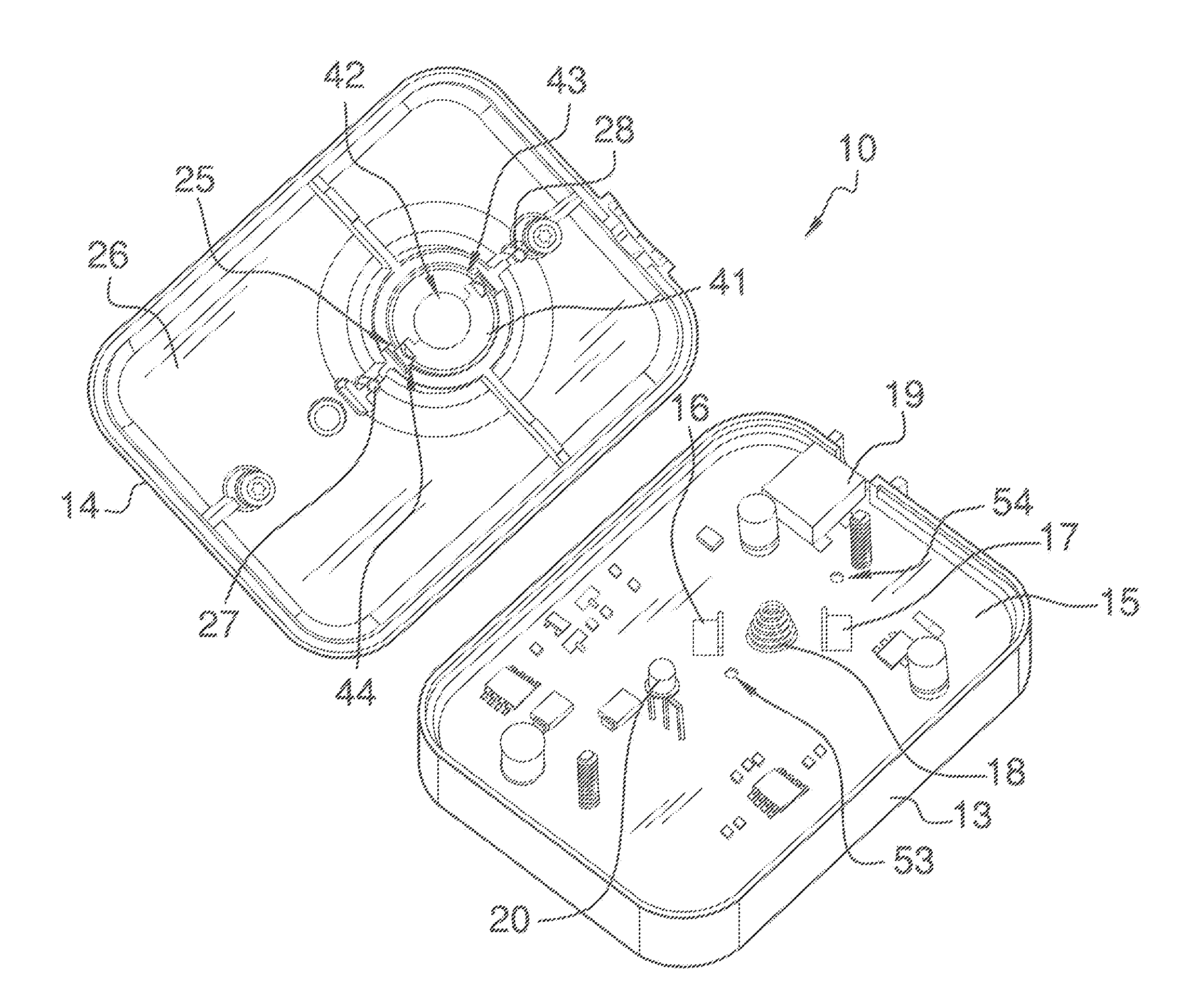
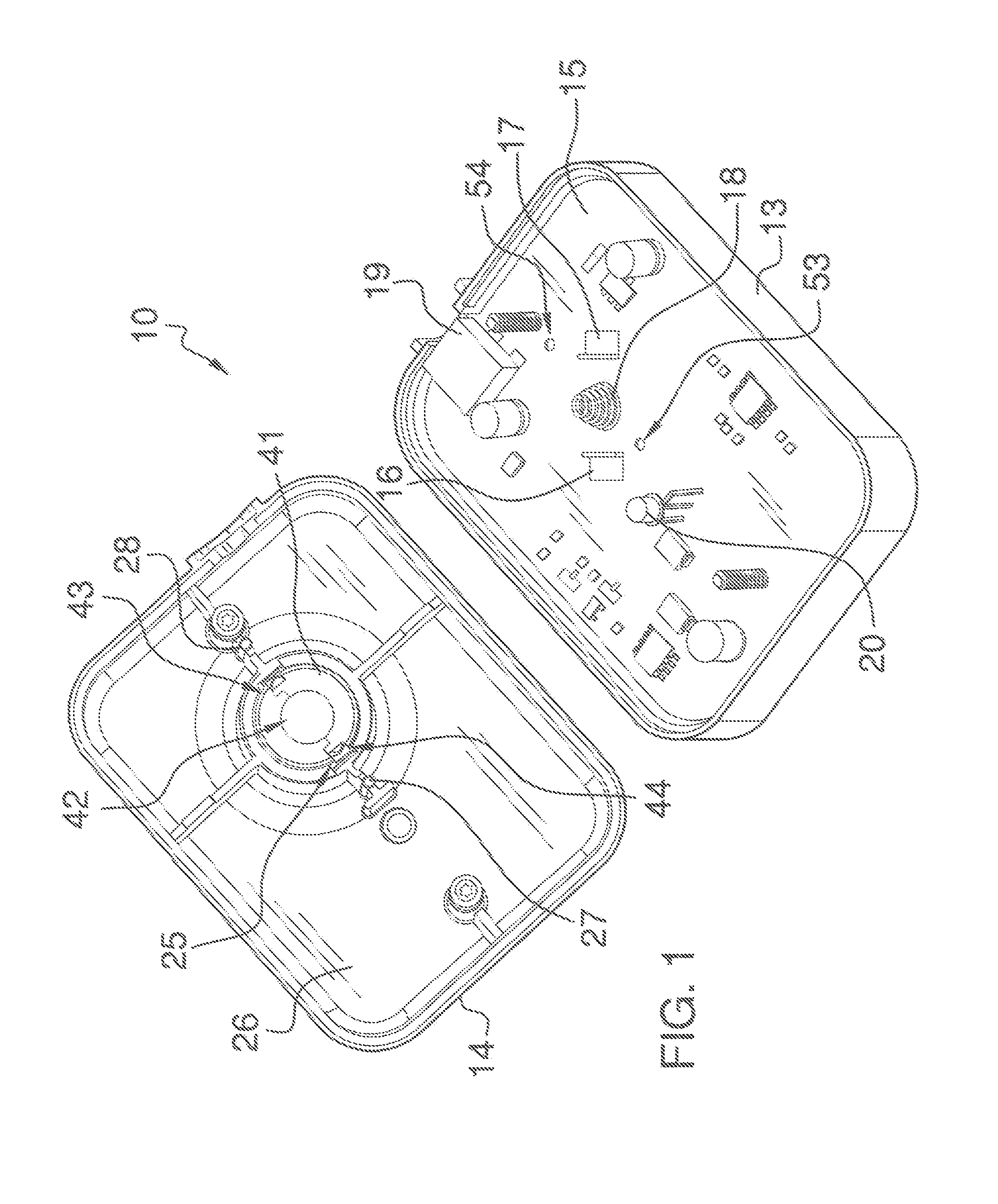
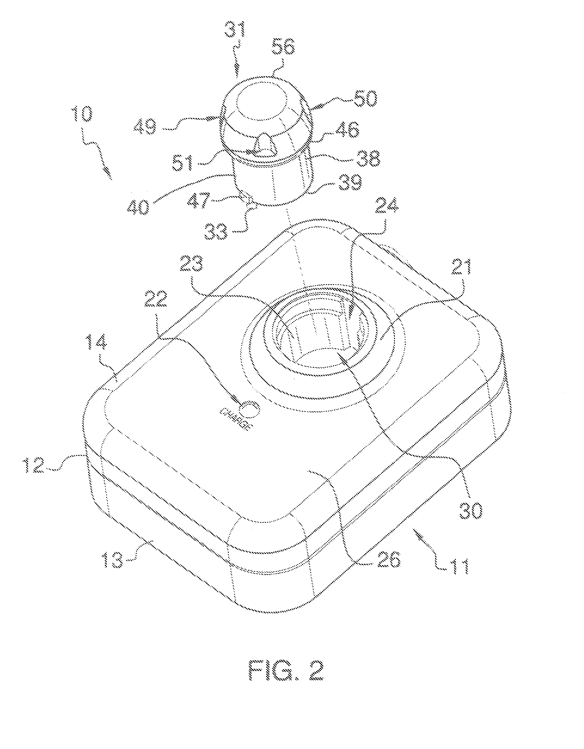
[0018]With reference now to the drawings, and in particular to FIGS. 1 through 3 thereof, a new invisible fence battery charger embodying the principles and concepts of the present invention and generally designated by the reference numeral 10 will be described.

[0019]As best illustrated in FIGS. 1 through 3, the invisible fence battery charger 10 generally comprises a battery charging unit 11 including a housing 12 and also including a circuit board 15 being conventionally disposed in the housing 12; and a battery pack 31 including a battery 32 being communicable with the battery charging unit 11 when being charged in the battery charging unit 11.

[0020]The circuit board 15 includes electrical contacts 16-18 being conventionally disposed upon the circuit board 15 and being communicable with the battery 32 for energizing the battery 32 and also includes a light emitting diode 20 being conventionally disposed upon and extending outwardly from the circuit board 15 and being communicable...


PUM


Abstract

An invisible fence battery charger for dramatically reducing homeowner's yearly invisible fence operating costs and reducing disposal of non-rechargeable batteries. The invisible fence battery charger includes a battery pack including a battery with battery terminals being in communication with the battery.

Description

BACKGROUND OF THE INVENTION[0001]1. Field of the Invention[0002]The present invention relates to battery packs and more particularly pertains to a new invisible fence battery charger for dramatically reducing homeowner's yearly invisible fence operating costs and reducing disposal of non-rechargeable batteries.[0003]2. Description of the Prior Art[0004]The use of battery packs is known in the prior art. More specifically, battery packs heretofore devised and utilized are known to consist basically of familiar, expected and obvious structural configurations, notwithstanding the myriad of designs encompassed by the crowded prior art which have been developed for the fulfillment of countless objectives and requirements.[0005]One prior art includes a Control Station with Integrated Collar Recharging Docking Station for Pet Electronics Products, comprising a battery recharging docking station powered by an AC / DC converter that receives a corresponding collar / receiver assembly worn by the...

Claims


Application Information

Patent Timeline
Patent Type & Authority Patents(United States)
IPC IPC(8): G08B21/00
CPCH02J7/0042H02J7/0045G08B21/00
Inventor GRONNEBERG, JEFFREY, BRYAN
Owner GRONNEBERG JEFFREY BRYAN
Why Eureka
Try Eureka