Rotating device

a rotating device and fastening technology, applied in the direction of sliding contact bearings, record information storage, instruments, etc., can solve the problems of lubricant becoming likely to fly off, reducing the amount of held lubricant, and unsuitable formers, etc., to maintain or improve the rigidity of the bearing of the rotating device, the effect of thinning the rotating devi

Inactive Publication Date: 2014-04-29
SAMSUNG ELECTRO MECHANICS JAPAN ADVANCED TECHNOLOGY CO LTD
View PDF12 Cites 3 Cited by
  • Summary
  • Abstract
  • Description
  • Claims
  • Application Information

AI Technical Summary

Benefits of technology

[0008]The present invention has been made in view of the above-explained circumstances, and it is an object of the present invention to provide a rotating device that can advance a thinning while maintaining or improving the rigidity of a bearing unit.
[0013]According to the present invention, it becomes possible to accomplish a thinning of a rotating device while maintaining or improving the bearing rigidity of the rotating device.

Problems solved by technology

The former case is an inversed approach to the current trends for thinning of the disk drive devices, and thus the former case is not suitable.
The latter case brings about a technical disadvantage such that the amount of held lubricant decreases, and the sealing function becomes weak, and thus the lubricant becomes likely to fly off.
Such technical disadvantages may occur in the case of not only disk drive devices but also other kinds of rotating devices, in particular, rotating devices having a shaft included in a fixed body and employing a fluid dynamic bearing mechanism.

Method used


Image

  • Rotating device
  • Rotating device
  • Rotating device

Examples


Embodiment Construction

[0018]In the following explanation, the same or corresponding component and member in respective figures are denoted by the same reference numeral, and the duplicated explanation thereof will be omitted accordingly. Moreover, the dimension of the member in each figure is enlarged or reduced as needed in order to facilitate understanding to the present invention. A portion of the member not important to explain an embodiment of the present invention in each figure is illustrated in an omitted manner.

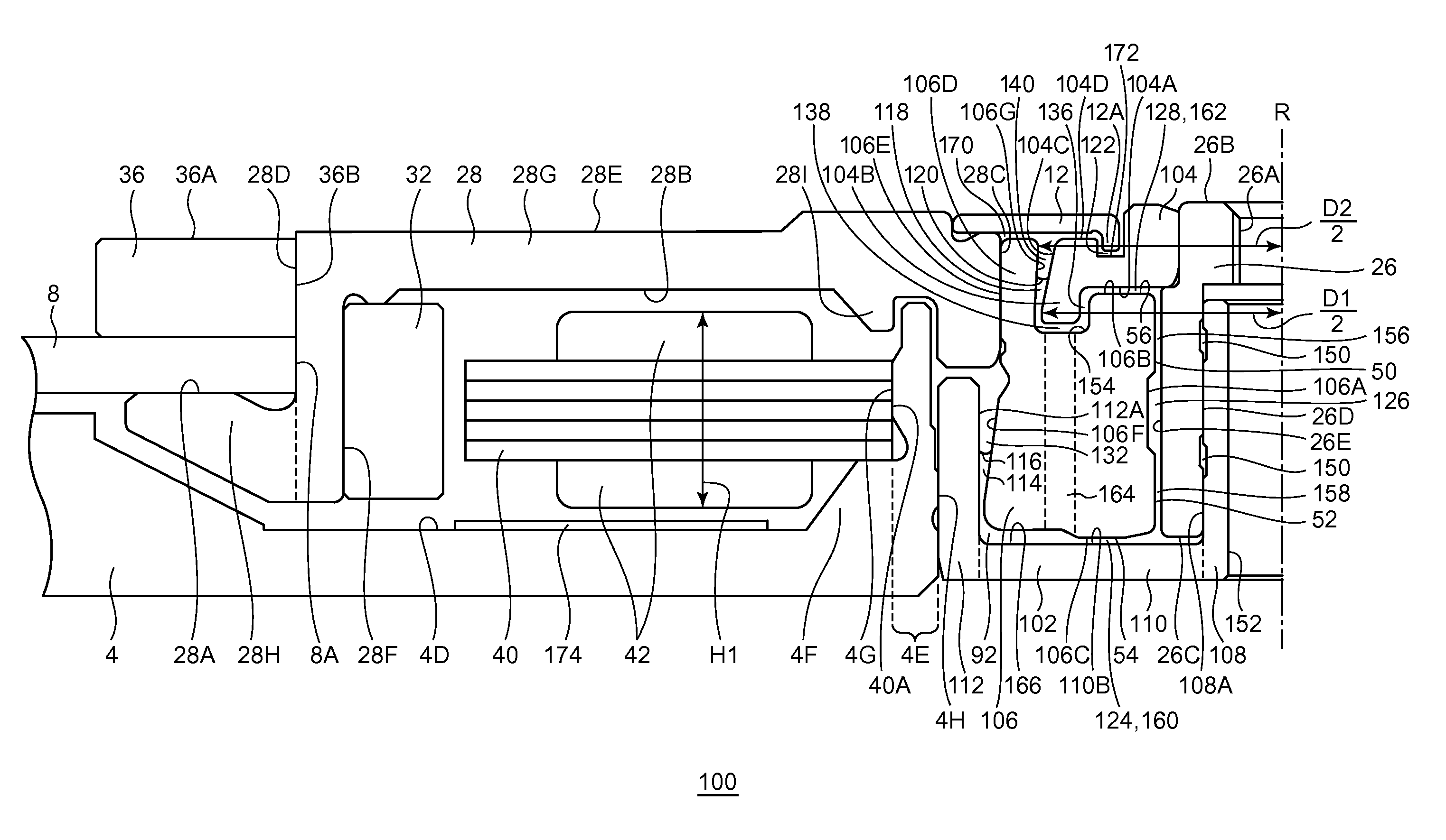
[0019]A rotating device according to an embodiment of the present invention is suitably utilized as a disk drive device like a hard disk drive on which a magnetic recording disk is to be loaded and which rotates such a magnetic recording disk, in particular, a fastened-shaft type disk drive device which has a shaft fastened to a base and has a hub rotatable with respect to the fastened shaft.

[0020]According to the rotating device of this embodiment, a tapered seal including an air-liquid ...


PUM

PropertyMeasurementUnit
diameteraaaaaaaaaa
thicknessaaaaaaaaaa
thicknessaaaaaaaaaa

Abstract

A rotating device includes a sleeve which encircles a shaft, a housing which supports the shaft and which forms an annular supporting recess where the lower end of the sleeve enters together with the shaft, a ring member which is provided above the sleeve and which is fixed to the shaft in a manner encircling the shaft. A first gap between the sleeve and the shaft includes first and second radial dynamic pressure generating portions. An annular sleeve recess is formed in upper face of the sleeve. The ring member includes a ring entering portion that enters the sleeve recess in a non-contact manner. An outward gap in the radial direction where the ring entering portion and the sleeve recess face with each other in the radial direction includes a second air-liquid interface of a lubricant.

Description

BACKGROUND OF THE INVENTION[0001]1. Field of the Invention[0002]The present invention relates to a fastened-shaft type rotating device.[0003]2. Description of the Related Art[0004]Disk drive devices like hard disk drives are becoming compact and increasing the capacity, and loaded in various electronic devices. In particular, loading of such disk drive devices in portable electronic devices, such as a laptop computer and a portable music player, is advancing. Disk drive devices loaded in such portable electronic devices need improvement of the shock-resistant performance and the vibration-resistance performance so as to withstand against a shock due to falling and a vibration during a carriage in comparison with ones loaded in stationary electronic devices like a desktop personal computer.[0005]For example, JP 2009-162246 A and JP 2010-127448 A disclose motors which have a shaft fastened to a base plate and which employ a fluid dynamic bearing as a bearing mechanism.SUMMARY OF THE I...

Claims


Application Information

Patent Timeline
Patent Type & Authority Patents(United States)
IPC IPC(8): G11B19/20
CPCF16C33/745G11B19/2009G11B5/012H02K7/08H02K7/086H02K5/1677G11B19/2036F16C17/107F16C2370/12
Inventor KODAMA, MITSUOMIZUNO, MASAFUMINONAKA, TAKETO
Owner SAMSUNG ELECTRO MECHANICS JAPAN ADVANCED TECHNOLOGY CO LTD
Why Eureka
Try Eureka