
High velocity burner apparatus and method

a burner and high-speed technology, applied in the direction of lighting and heating equipment, combustion types, separation processes, etc., can solve the problems of limiting the usefulness of such burners, adding time and cost in cleaning and repairing, and legion of prior-art devices

Inactive Publication Date: 2014-05-06
STRATEGIC ENVIRONMENTAL SOLUTIONS
View PDF17 Cites 5 Cited by
  • Summary
  • Abstract
  • Description
  • Claims
  • Application Information

AI Technical Summary

Problems solved by technology

Problems with prior art devices are legion.
These requirements result in added time and costs in cleaning and repairing and replacing injectors thus limiting the usefulness of such burners.
When prior art burners are designed to accommodate more basic, less refined fuels containing some amount of solid material, these input, injector, problems are exacerbated.
Additionally, prior art burners of less refined fuels, bio fuels, etc., often create unacceptably high levels of toxic byproducts such as toxic smoke, gas, and residue which must be treated and properly disposed.
This greatly limits the attractiveness of non-standard, “green” fuels and the like.
This results, however, in adding expense and complexity to the burner and thus limits the usefulness of this strategy.

Method used


Image

  • High velocity burner apparatus and method
  • High velocity burner apparatus and method
  • High velocity burner apparatus and method

Examples


Embodiment Construction

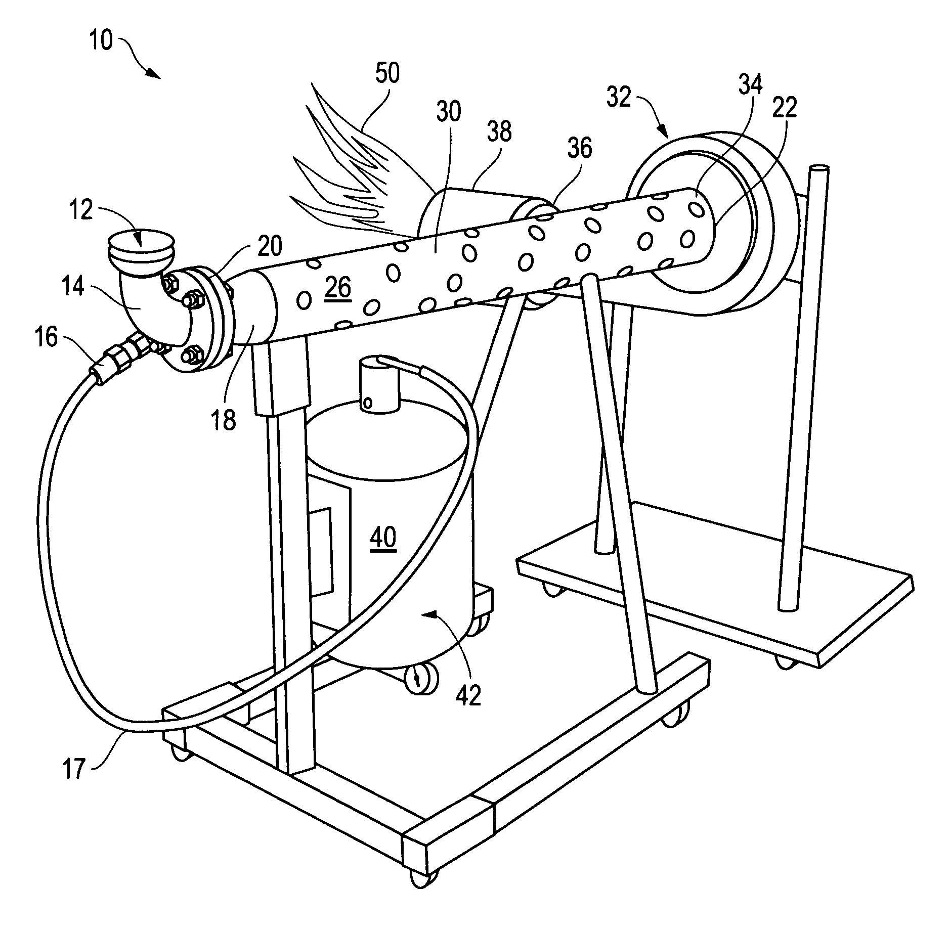
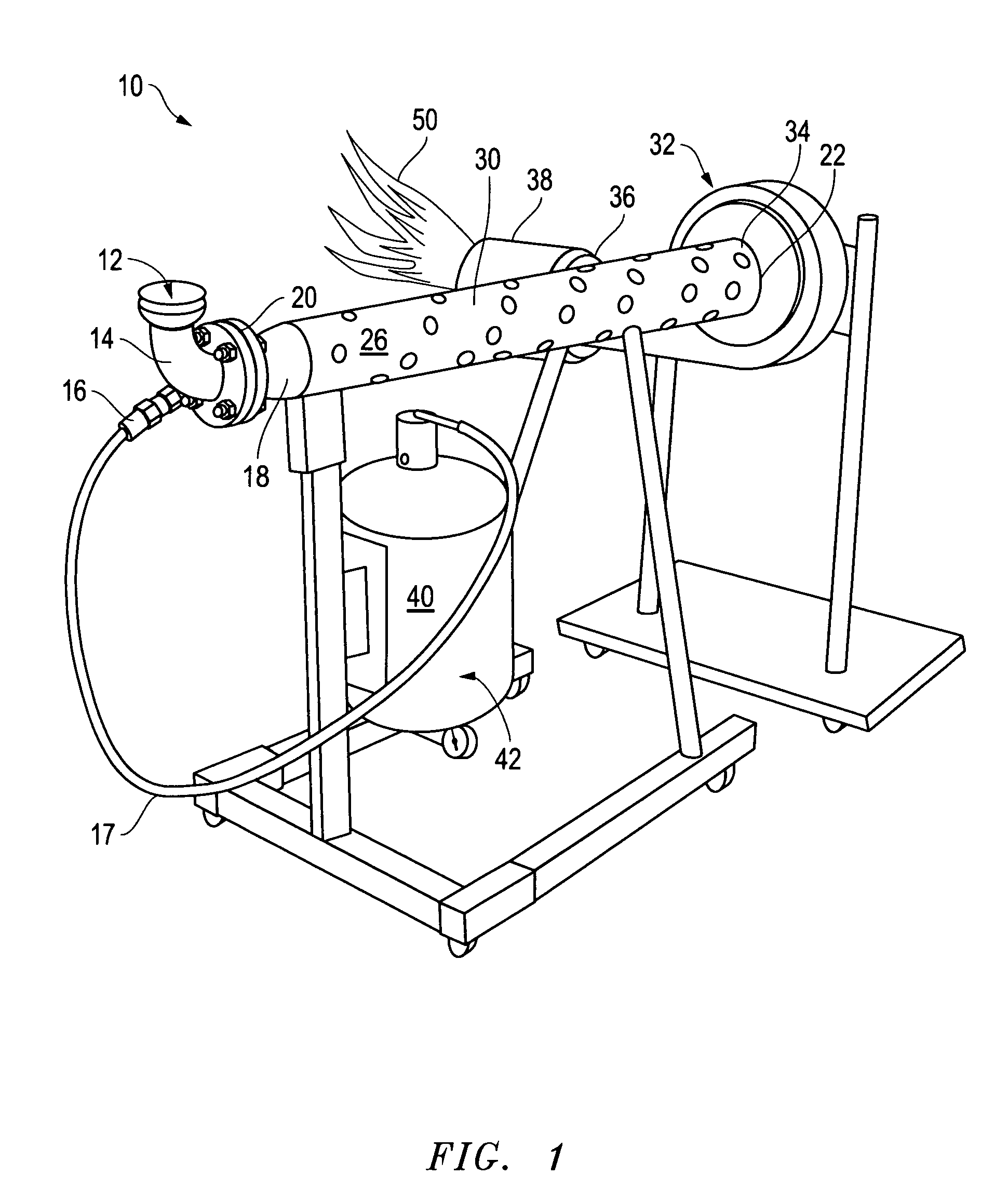
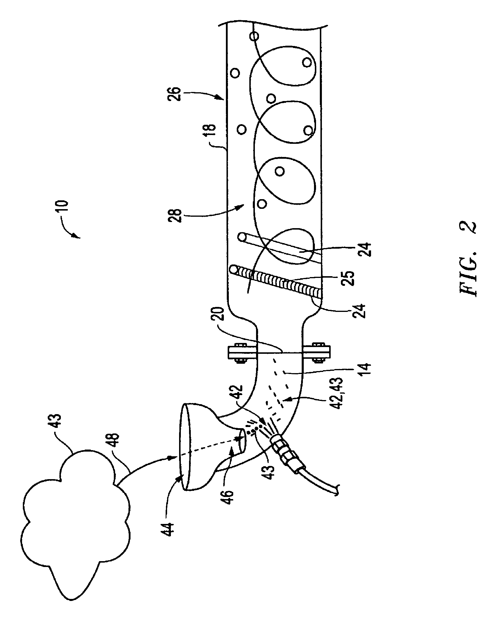
[0019]The preferred embodiment of the present invention is illustrated by way of example in FIGS. 1-3. With specific reference to FIG. 1, high velocity burner 10 includes and air intake funnel 12. An air-fluid mixer 14 is connected with the air intake funnel 12. Fluid input 16 is connected with air-fluid mixer 14. Magnetic tube container 18 has an entrance 20 and an exit 22. Entrance 20 is connected with air fluid mixer 14.

[0020]Magnetic tubes 24 are connected inside of magnetic tube container 18. In that regard, magnetic tube container has an outside 26 and an inside 28 formed of sides 30. As shown in the figures, magnetic tube container 18 is tube shaped itself as in the form of a pipe with a unitary side 30. Certainly, there is no limitation as to the geometry of magnetic tube container 18 and it could be any desired form so long as it included an inside 28 for the containment of magnetic tubes 24. In the same manner, magnetic tubes 24 are preferably pipe shaped tubes as illustra...


PUM

PropertyMeasurementUnit
speedsaaaaaaaaaa
diameteraaaaaaaaaa
suctionaaaaaaaaaa

Abstract

A high velocity burner apparatus and method includes an air intake funnel and an air-fluid mixer connected with the air intake funnel. A fluid input is connected with the air-fluid mixer. A magnetic tube container with an entrance and an exit is provided where the entrance is connected with the air-fluid mixer and where the magnetic tube container includes a plurality of individual magnetic tubes connected within the magnetic tube container such that adjacent magnetic tubes are misaligned with each other. An air suction device is connected with the exit of the magnetic tube container such that suction is applied through the magnetic tube container to the air intake funnel and a burner device is connected with the air suction device for burning fluid that passes through the magnetic tube container.

Description

FIELD OF THE INVENTION[0001]This invention relates to a high velocity burner apparatus and method. In particular, in accordance with one embodiment, the invention relates, to a high velocity burner apparatus with an air intake funnel and an air-fluid mixer connected with the air intake funnel. A fluid input is connected with the air-fluid mixer. A magnetic tube container with an entrance and an exit is provided where the entrance is connected with the air-fluid mixer and where the magnetic tube container includes a plurality of individual magnetic tubes connected within the magnetic tube container such that adjacent magnetic tubes are misaligned with each other. An air suction device is connected with the exit of the magnetic tube container such that suction is applied through the magnetic tube container to the air intake funnel and a burner device is connected with the air suction device for burning fluid that passes through the magnetic tube container.BACKGROUND OF THE INVENTION[0...

Claims


Application Information

Patent Timeline
Patent Type & Authority Patents(United States)
IPC IPC(8): F02M27/04
CPCF23D14/02F23C99/001F23D14/62
Inventor GARRISON, ROY, LEE
Owner STRATEGIC ENVIRONMENTAL SOLUTIONS
Learn More