Busbar adapter comprising a mounting rail for attaching a switching device

a technology for switching devices and adapters, which is applied in the direction of coupling device connections, substation/switching arrangement details, substation/switching arrangement boards/panels/desks, etc., can solve problems such as technical tools, and achieve the effect of confering additional stability to the produced connection

Active Publication Date: 2014-05-06
RITTALWERK RUDOLF LOH GMBH & CO KG
View PDF44 Cites 3 Cited by
  • Summary
  • Abstract
  • Description
  • Claims
  • Application Information

AI Technical Summary

Benefits of technology

[0014]In a further embodiment of the invention it is provided that the mounting rail comprises two parallel rows of leg elements which are arranged equidistantly to another. Furthermore, the busbar adapter comprises two parallel rows of passages which are equidistantly arranged, wherein the distance corresponds to that of the leg elements. It is provided that the distance of the parallel rows of passages is identical to the distance of the parallel rows of leg elements. Preferably, the leg elements are provided at parallel longitudinal sides of the mounting rail, wherein leg elements may be provided over the entire length of said longitudinal sides. Thereby, an anti-twist locking of the mounting rail on the busbar adapter is possible.
[0015]For particularly stable attachment of the mounting rail at the busbar adapter it may be provided that at least one of the leg elements comprises a first guiding surface and a second guiding surface is arranged, viewed in insertion direction, in front of at least one of the passages, wherein the first and the second guiding surfaces are positively contacting each other when the mounting rail is attached to the busbar adapter. In this embodiment, the leg elements have, in addition to the function to produce a positive connection with the busbar adapter, the supplemental function to confer additional stability to the produced connection between both components, in particular in view of twists in a plane perpendicular to the insertion direction of the leg elements through the passages, by means of a positive connection between corresponding guiding surfaces of the leg element and the busbar adapter.

Problems solved by technology

An essential disadvantage of a busbar adapter known from the prior art consists in that at least for releasing locking between the busbar adapter and a mounting rail sitting on it, always technical tools such as, for example, screw drivers or the like, are needed.

Method used


Image

  • Busbar adapter comprising a mounting rail for attaching a switching device
  • Busbar adapter comprising a mounting rail for attaching a switching device
  • Busbar adapter comprising a mounting rail for attaching a switching device

Examples


Embodiment Construction

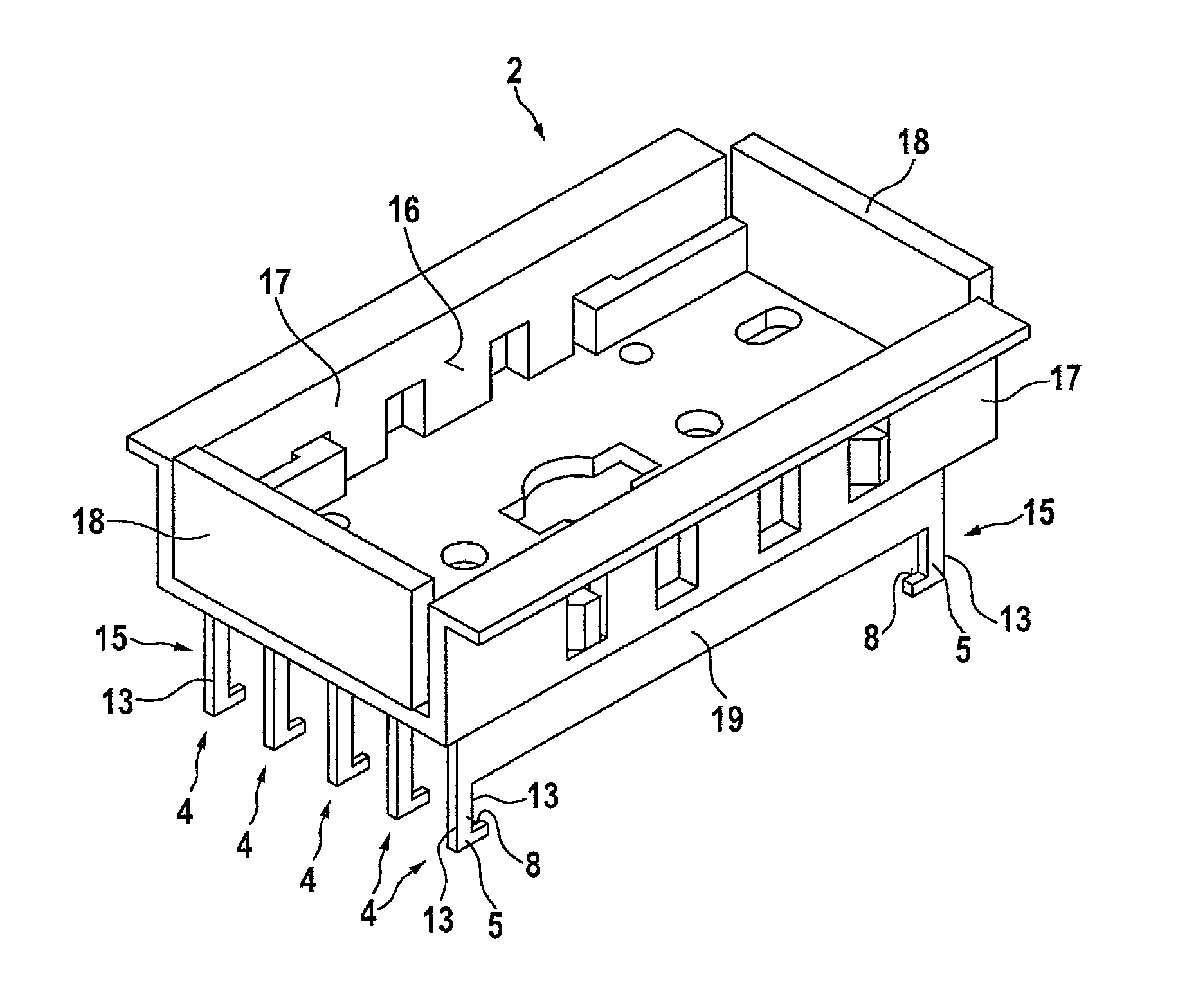
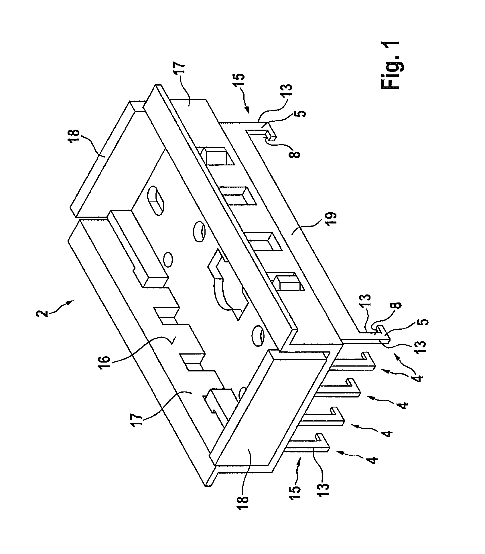
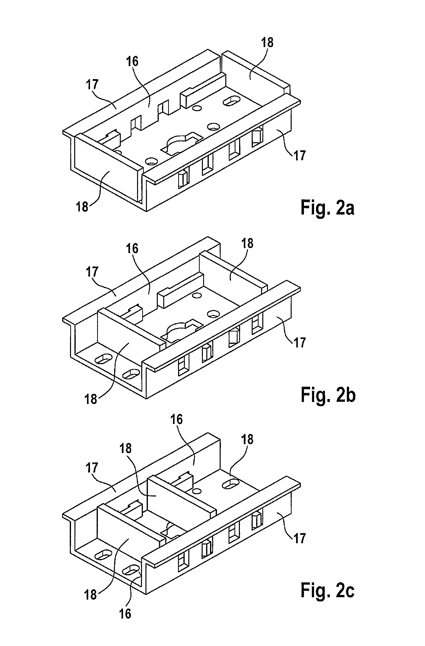
[0024]FIG. 1 shows a mounting rail 2 according to the invention consisting substantially of a base plate 19 and a U beam attached thereto, wherein the U beam comprises two flanges 17 including parallel running inner surfaces 16. End pieces 18 are provided to be variably latched in longitudinal direction of the U beam. Further, leg elements 4 are formed at base plate 19 which comprise a shaft 15 having essentially rectangular cross section, wherein three of the side faces of shaft 15 are formed as first guiding surfaces 13 and a latch 5 is formed at the fourth guiding surface 13. Guiding surfaces 13 are provided to positively contact corresponding second guiding surfaces of the busbar adapter when mounting rail 2 is positioned on a busbar adapter. At the free ends of leg elements 4, a respective latch 5 is provided which includes a retaining surface 8. The retaining surface 8 is in so far essential for the invention, as it is embodied to form a distance in an inserting state of the m...


PUM


Abstract

A busbar adapter has a mounting rail for attaching a switching device to the busbar adapter, wherein the mounting rail can be attached to the busbar adapter at different positions. The mounting rail includes leg elements and the busbar adapter includes passages through which a respective one of the leg elements of the mounting rail extend with a latch from a first boundary surface of the passages on which the mounting rail rests, to a second boundary surface of the passages, such that the respective latch of the leg elements is, with a retaining surface thereof, arranged in a distance to the second boundary surface which corresponds to a dimension of a slider positively insertable between the retaining surface and the second boundary surface.

Description

BACKGROUND OF THE INVENTION[0001]The invention relates to a busbar adapter comprising a mounting rail for attaching a switching device to the busbar adapter, wherein said mounting rail can be attached to the busbar adapter at different positions.[0002]Generic busbar adapters are known in various embodiments, in particular in view of the attachment of the mounting rail to the busbar adapter.[0003]DE 202 11 940 U1 discloses a busbar adapter wherein the mounting rail is clamped on the busbar by means of an actuating element which may be displaced during mounting with the aid of a screw driver.[0004]It is known from DE 42 42 704 C2 to attach the mounting rail to the busbar adapter either directly with the aid of two screws or, instead of these screws, to provide dome-like hollow protrusions which are slotted in longitudinal direction.[0005]Thereby, it is provided that the mounting rail engages into provided openings of a hole rail of the busbar adapter with its dome-like protrusions, wh...

Claims


Application Information

Patent Timeline
Patent Type & Authority Patents(United States)
IPC IPC(8): H01R25/00H02B1/04
CPCH02B1/21
Inventor KAYMA, JOERGPLATH, PIERREKUESTER, FRANKKIENHOLZ, MATTHIAS
Owner RITTALWERK RUDOLF LOH GMBH & CO KG
Why Eureka
Try Eureka