
Implantable pulse generator with multiple suture ports

a pulse generator and suture port technology, applied in the field of implantable medical devices, can solve the problems of ipgs that cannot be re-positioned, moved laterally, rotating, or inverting, and the device is ineffective in performing the intended function, and achieves the effect of facilitating implantation, maximizing the internal volume of housing components, and facilitating implantation

Active Publication Date: 2019-12-26
GALVANI BIOELECTRONICS LTD +1
View PDF0 Cites 2 Cited by
  • Summary
  • Abstract
  • Description
  • Claims
  • Application Information

AI Technical Summary

Benefits of technology

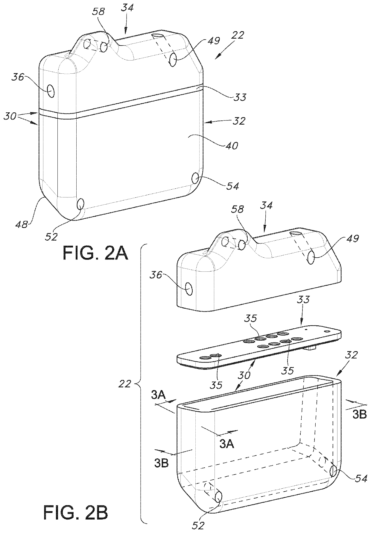
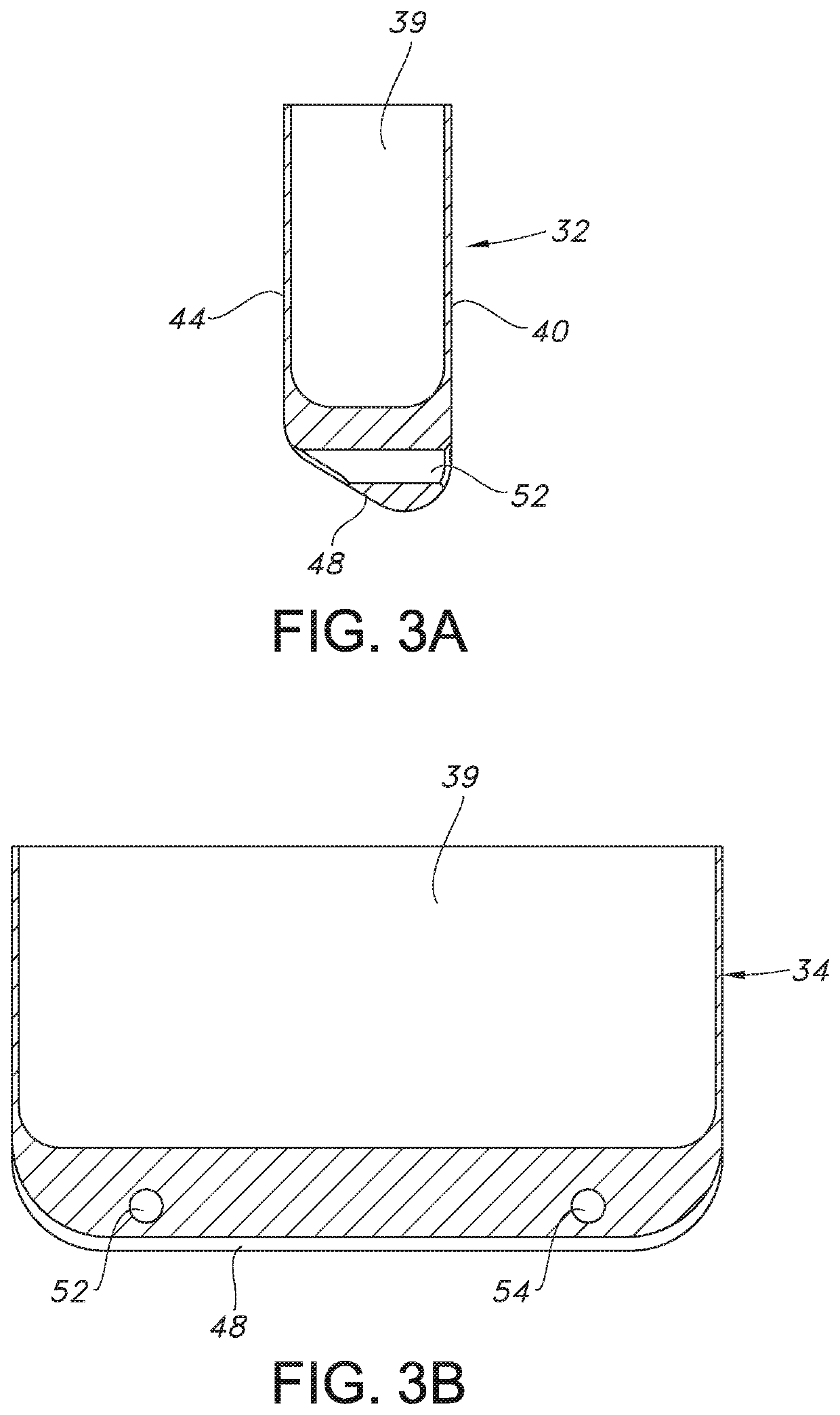
The present disclosure solves the problem of immobilizing an implantable pulse generator (IPG) in the body of a patient by integrating fastening features into the housing of the IPG. This allows for easier implantation and maximizes internal volumes for housing components. The device is designed with a triangular attachment configuration that provides a more stable attachment to the patient. Additionally, the device is fabricated with a sloping surrounding edge wall that reduces the patient's ability to externally manipulate the device and impart forces on it that would cause it to translate or rotate from its intended position. The invention simplifies the manufacturing process and reduces costs and cycle time.

Problems solved by technology

The problem of an implanted IPG moving laterally, rotating, or inverting is even more pronounced for smaller IPGs.
Such unintended migration may render the device ineffective in performing its intended function, ineffective for remote induction recharging, and / or may cause other medical complications in the patient.
In manufacturing IPGs, such a welding task is difficult for a human to perform on a consistent basis.
Providing robotic welding machines in a manufacturing plant adds a significant capital equipment cost, and the programming, oversight, and maintenance of the robots add significant operating costs.
Moreover, even with the relatively precise operation of robots, adjustment of them is often needed, which is disruptive to manufacturing IPGs in high volumes.
During welding, the presence of any dust or other contaminants may weaken a welded joint.
Programming, operation, and maintenance of the equipment and documentation and archiving of the resulting data add to operational costs.
In addition to the capital and operating costs, the steps of welding and inspection add to the overall cycle time of the IPG manufacturing process, thus reducing the throughput of the manufacturing operation.
Other problems related to preparation of an IPG for implantation, the implantation procedure, and the ongoing use of the device in a patient may also occur.
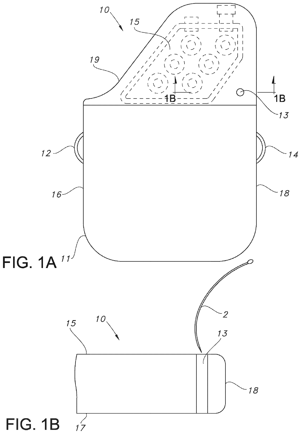
The welds of the wire loops to the titanium enclosure are prone to trapping pathogens and causing failure of IPG sterilization procedures.
Further, the welded wire loops may cause tissue erosion or irritation in a patient due to their relatively sharp edges on the perimeter of the IPG housing.
This can enable migration of the device in the patient, rendering its function useless.
Such a suture port 13 is also problematic because it is difficult for a surgeon to pass a surgical needle 2 carrying a suture (not shown) through the relatively long passageway of the suture port 13.
A needle of relatively large radius may be required, which is incompatible with the need for the suturing to be of limited depth into the body tissue.
Thus, any suture ports having the structure of suture port 13 will result in a reduced volume for internal device components, which is undesirable.
This is referred to as “twiddlers syndrome”, and can cause damage to the device system or injury to the patient.
The inward sloping surrounding edge wall of the device reduces the patient's ability to externally manipulate the device and impart forces on the device that would cause it to translate or rotate from its intended position.

Method used


Image

  • Implantable pulse generator with multiple suture ports
  • Implantable pulse generator with multiple suture ports
  • Implantable pulse generator with multiple suture ports

Examples


Embodiment Construction

[0033]For a general understanding of the present invention, reference is made to the drawings. In the drawings, like reference numerals have been used throughout to designate identical elements. The drawings are to be considered exemplary, and are for purposes of illustration only. The dimensions, positions, order, relative sizes, device shapes, and suture hole shapes reflected in the drawings provided herewith may vary.

[0034]In the following disclosure, the present invention is described in the context of its use as an implantable pulse generator used for medical purposes in a human or animal. However, it is not to be construed as being limited only to use in generating electrical pulses for therapeutic purposes. The invention is adaptable to any use in which it is desirable to implant and secure a compact device in human or animal body tissue. Additionally, the description may identify certain components with the adjectives “front,”“rear,”“top,”“upper,”“bottom,”“lower,”“left,”“rig...


PUM


Abstract

A device that is implantable in body tissue of a human or animal. The device is comprised of a header comprising at least one terminal adapted for removable connection to a lead and an open ended case closed by a plate to form a housing. The housing is comprised of a surrounding edge wall joined to a first side wall and a second side wall opposed to the first side wall. At least a first suture port extends through the edge wall and the second side wall but not the first side wall at an upper edge region of the housing. A second suture port may extend through the surrounding edge wall and the second side wall but not the first side wall in a similar manner. A third suture port may extend through the header. The three suture ports may define a triangular attachment configuration.

Description

CROSS-REFERENCE TO RELATED PATENT APPLICATIONS[0001]This application claims the benefit of U.S. Provisional Patent Application No. 62 / 688,415, filed Jun. 22, 2018, the disclosure of which is incorporated herein by reference. The above benefit claim is being made in an Application Data Sheet submitted herewith in accordance with 37 C.F.R. 1.76 (b)(5) and 37 C.F.R. 1.78.BACKGROUNDTechnical Field[0002]The present disclosure relates to implantable medical devices that generate and disperse electrical energy into human or animal body tissues. More particularly, it relates to implantable medical devices that are configured to facilitate surgical implantation procedures, and to resist migration subsequent to implantation.Description of Related Art[0003]An implantable pulse generator (IPG) is a device that is capable of generating pulses of electrical energy that are dispersed into human or animal body tissue for a medical purpose. Examples of IPGs are cardiac pacemakers, cardioverter-defib...

Claims


Application Information

Patent Timeline
IPC IPC(8): A61N1/375
CPCA61N1/3758A61N1/37514A61N1/0539A61N1/37512A61N1/0534A61N1/0558A61N1/37518
Inventor ARMESTO, IGNACIO A.VILLAMIL, LUIS DANIELYAZICIOGLU, REFET FIRATSCHLEGEL, KRISTINALEYDE, KENT
Owner GALVANI BIOELECTRONICS LTD
Learn More