Catalyst carrier body with corrugated casing and process for producing the same

a carrier body and corrugated casing technology, applied in the direction of machine/engine, separation process, lighting and heating apparatus, etc., can solve the problems of reducing the length available for bending the corrugated casing or lateral casing, and reducing the service life of the corrugated casing under operating conditions. , to achieve the effect of stable attachment of the honeycomb body and simple construction

Active Publication Date: 2009-01-13
EMITEC GESELLSCHAFT FUR EMISSIONSTECHNOLOGIE MBH
View PDF37 Cites 2 Cited by
  • Summary
  • Abstract
  • Description
  • Claims
  • Application Information

AI Technical Summary

Benefits of technology

[0010]It is accordingly an object of the invention to provide a catalyst carrier body with a corrugated casing and a process for producing the same, which overcome the hereinafore-mentioned disadvantages of the heretofore-known products and processes of this general type and which provide a connection between a honeycomb body and a housing that is as durable as possible, in particular for honeycomb bodies made from thin metal sheets. In addition, the catalyst carrier body is to have a simple construction and to ensure stable attachment of the honeycomb body even under high thermal and dynamic loads. Furthermore, it is a primary requirement that the process be easy to carry out as part of series production.

Problems solved by technology

However, those produce much larger attachment surface areas than required for mechanically secure holding of the honeycomb body.
Those attachment surfaces in particular have a large extent in the direction of the longitudinal axis, with the result that the length available for bending the corrugated casing or lateral casing is shortened, leading to faster destruction of the corrugated casing under operating conditions.
Of course, the total surface area of the attachment sections must not become so small that they are no longer able to reliably hold the honeycomb body under dynamic loads.

Method used


Image

  • Catalyst carrier body with corrugated casing and process for producing the same
  • Catalyst carrier body with corrugated casing and process for producing the same
  • Catalyst carrier body with corrugated casing and process for producing the same

Examples


Embodiment Construction

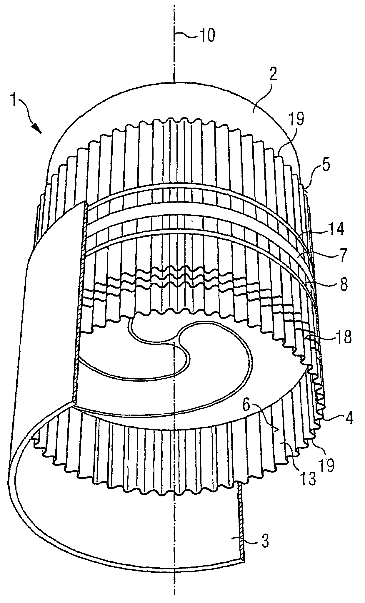
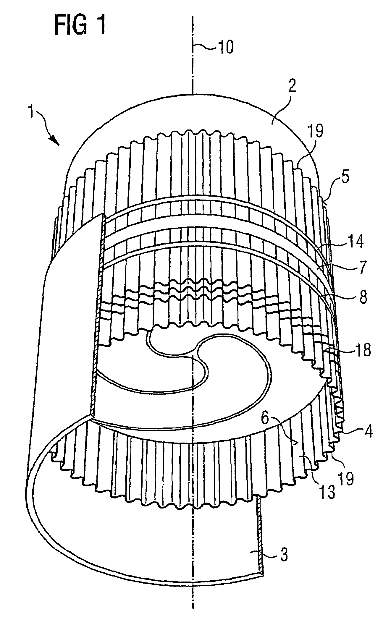
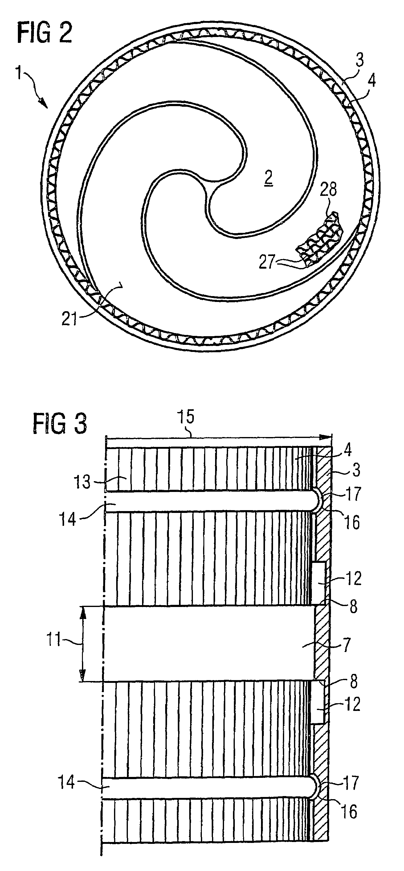
[0037]Referring now to the figures of the drawings in detail and first, particularly, to FIG. 1 thereof, there is seen a diagrammatic and perspective illustration of one configuration of a catalyst carrier body 1, including a honeycomb body 2 and a housing 3. A corrugated casing 4 having an outer side 5 and an inner side 6 is disposed between the honeycomb body 2 and the housing 3. The outer side 5 of the corrugated casing 4 is connected to the housing 3 by technical joining and the inner side 6 of the corrugated casing 4 is connected to the honeycomb body 2 by technical joining. In this case, the centrally disposed connection of the corrugated casing 4 to the housing 3 by technical joining is executed through the use of a strip of brazing material 7. In order to prevent this strip of brazing material 7 or the brazing material which it contains from penetrating into undesired regions during a heat treatment of the catalyst carrier body 1, the corrugated casing 4 is provided with two...


PUM

PropertyMeasurementUnit
widthaaaaaaaaaa
widthaaaaaaaaaa
widthaaaaaaaaaa

Abstract

A catalyst carrier body has a geometrical longitudinal axis, a honeycomb body and a housing. A corrugated casing with an outer side and an inner side is disposed between the honeycomb body and the housing. The corrugated casing is connected to the housing at attachment sections on the outer side thereof by brazing. The attachment sections lie substantially on a common circumferential line and have the narrowest possible width in direction of a longitudinal axis. The attachment sections have an overall surface area permitting them to securely hold the honeycomb body under operating conditions. A high retention degree for the connection between the honeycomb body and housing can thus be achieved even with a shrinking of the diameter of the honeycomb body at end sides during the service life thereof.

Description

CROSS-REFERENCE TO RELATED APPLICATION[0001]This is a continuing application, under 35 U.S.C. § 120, of copending International Application No. PCT / EP03 / 02678, filed Mar. 14, 2003, which designated the United States; this application also claims the priority, under 35 U.S.C. § 119, of German Patent Application 102 17 259.5, filed Apr. 18, 2002; the prior applications are herewith incorporated by reference in their entirety.BACKGROUND OF THE INVENTIONFIELD OF THE INVENTION[0002]The present invention relates to a catalyst carrier body having a geometric longitudinal axis, a honeycomb body and a housing. A corrugated casing having an outer side and an inner side is disposed between the honeycomb body and the housing. The outer side of the corrugated casing is connected to the housing by technical joining at attachment sections and the inner side of the corrugated casing is connected to the honeycomb body by technical joining. The invention also relates to a process for producing the ca...

Claims


Application Information

Patent Timeline
Patent Type & Authority Patents(United States)
IPC IPC(8): B01D50/00F01N3/28
CPCF01N3/281F01N3/2853F01N3/2864Y10T29/49345F01N2350/04
Inventor MAUS, WOLFGANGKONIECZNY, JORG-ROMANKURTH, FERDISCHMIDT, UDOLOWEN, ALEXWIERES, LUDWIG
Owner EMITEC GESELLSCHAFT FUR EMISSIONSTECHNOLOGIE MBH
Why Eureka
Try Eureka