Inductor core, an arrangement for a press, and a manufacturing method

a technology of inductor core and manufacturing method, which is applied in the direction of transformer/inductance magnetic core, inductance with magnetic core, etc., can solve the problems of affecting the manufacturing process, reducing the stability reducing the efficiency of the inductor core, so as to improve the stability and stability. , the effect of increasing the heat dissipation

Active Publication Date: 2014-03-20
HOGANAS AB
View PDF11 Cites 2 Cited by
  • Summary
  • Abstract
  • Description
  • Claims
  • Application Information

AI Technical Summary

Benefits of technology

[0030]According to one embodiment the first surface comprises at least two recesses, said at least two recesses extending at least a part of a distance between the inner core portion and the outer core portion, and wherein the second surface, for each of said at least two recesses, comprises a protrusion oppositely arranged to a corresponding recess. Similar to the center protrusion and the rim protrusion, adding additional pairs or recesses and protrusions may enable a more stable attachment of the inductor core since the contact surface between the second surface and a mounting surface thereby may be increased. This may also enable increased heat dissipation from the inductor core.
[0031]According to one embodiment the at least two recesses and the corresponding protrusions present a symmetric angular distribution on the first and second surfaces. This may further improve the stability when attaching the inductor core to a mounting surface.

Problems solved by technology

The maximum possible pressure is limited inter alia by the capacity of the press, the size of the inductor core and the type of powder material which is being compressed.
However, the presence of the recess 14 and the slit 15 complicates the geometry and the structure of the inductor core 10 and affects the manufacturing process.
It has further been noticed that this problem becomes increasingly severe as the pressing force is increased and the size of the inductor core is increased.
However, a separate milling process increases the total manufacturing time and also requires additional tools, other than pressing tools, for completing the pot core.
Moreover, depending on the geometry of the inductor core and the material choice it may in some cases not be practically possible to mill a recess 14 and a slit 15 to a desired shape.
However, this results in a much more complicated and expensive press and tooling.

Method used


Image

  • Inductor core, an arrangement for a press, and a manufacturing method
  • Inductor core, an arrangement for a press, and a manufacturing method
  • Inductor core, an arrangement for a press, and a manufacturing method

Examples


Embodiment Construction

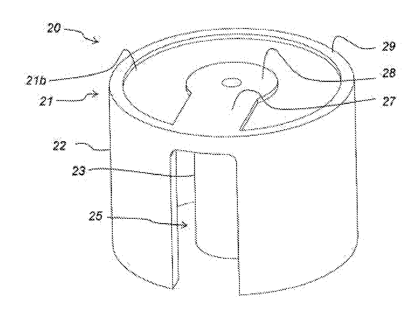
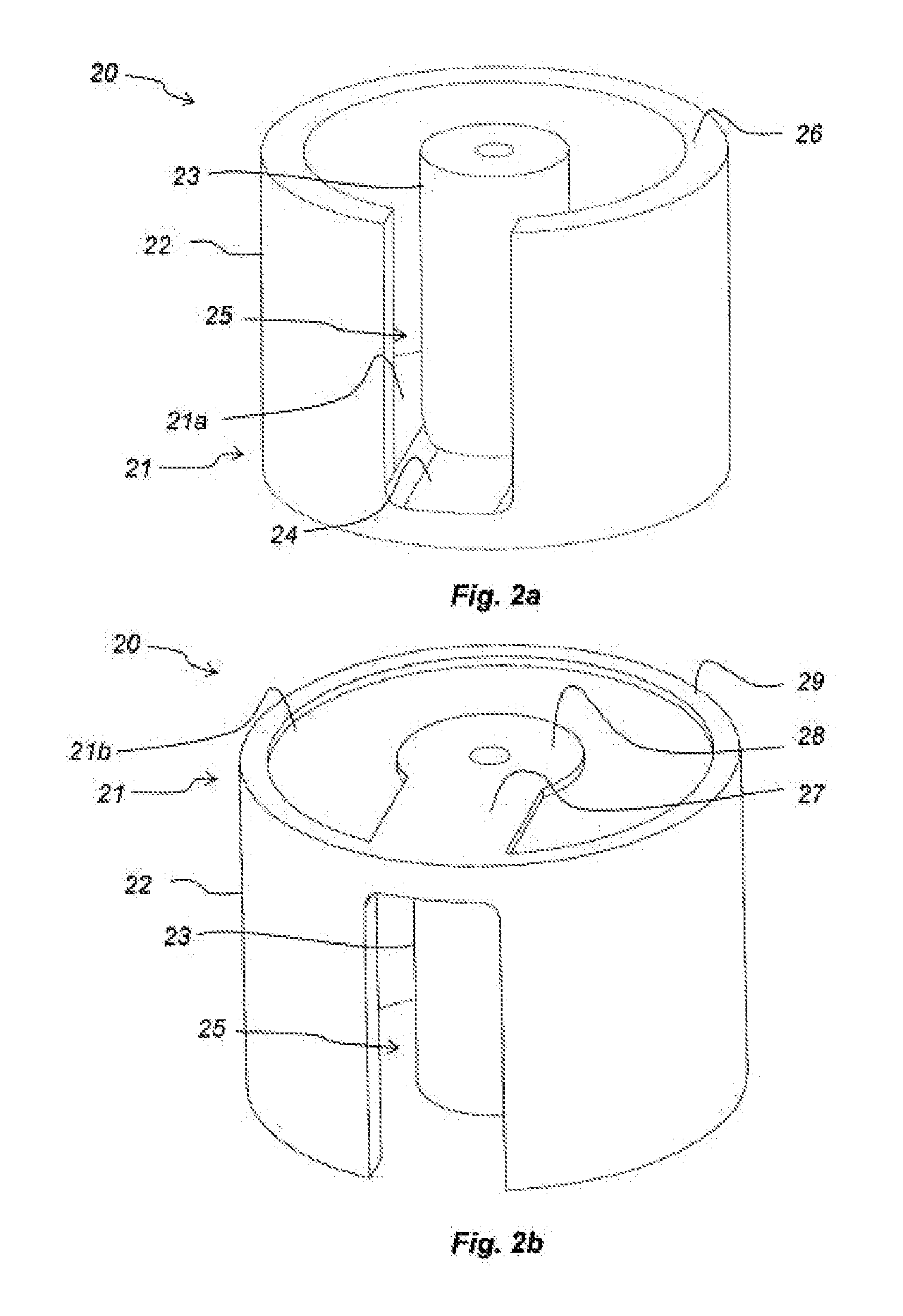
[0057]An embodiment of an inductor core 20 according to the present inventive concept will now be described with reference to FIGS. 2a and 2b.

[0058]The inductor core 20 may be made of a compressed soft magnetic powder material. The powder material may be a ferrite powder, a high purity iron powder, a Fe—Si powder, other silicon-alloyed powders, an iron-phosphorous alloy or some other powder material with similar properties. Optionally, the material may be a soft magnetic composite powder material including a soft magnetic powder (e.g. iron) provided with an electrically insulating coating. Examples of composite materials that may be used are Somaloy 110i, Somaloy 130i, Somaloy 500, Somaloy 700 and Somaloy 1000 which may be obtained from Höganäs AB, S-263 83, Höganäs, Sweden.

[0059]The inductor core 20 comprises a disc-shaped base core portion 21, extending in a radial direction. The base core portion 21 includes a first surface 21a and a second surface 21b opposite to the first surf...


PUM

PropertyMeasurementUnit
angleaaaaaaaaaa
angleaaaaaaaaaa
compressed soft magneticaaaaaaaaaa

Abstract

Inductor core including: a base core portion having a first surface and an opposite second surface; an inner core portion extending from the first surface in a direction transverse to the first surface; an outer core portion extending, in the direction transverse to the first surface, from the first surface to an end surface of the outer core portion, the outer core portion at least partly surrounding the inner core portion, thereby forming a space around the inner core portion for accommodating a winding; wherein the first surface includes a recess for accommodating a connection portion of the winding, said recess extending at least a part of a distance between the inner core portion and the outer core portion, and wherein the outer core portion presents a slit extending from said end surface towards the recess, and wherein the second surface comprises a first protrusion oppositely arranged to the recess.

Description

TECHNICAL FIELD[0001]The present inventive concept relates to an inductor core, an arrangement for a press and a manufacturing method.BACKGROUND OF THE INVENTION[0002]Inductors are used in a wide array of applications such as signal processing, noise filtering, power conversion, electrical transmission systems etc. In order to provide more compact and more efficient inductors, the electrically conducting winding of the inductor may be arranged in a magnetically conducting core, i.e. an inductor core.[0003]Inductor cores may be manufactured by pressing a soft magnetic powder material, e.g. an iron powder. The powder may be put into a cavity wherein the powder may be compacted. In some cases it may be desirable to compress the soft magnetic material powder to a high density in order to e.g. increase the magnetic saturation of the final inductor core etc. During manufacturing, this may be accomplished by increasing the pressure applied by the punches. The maximum possible pressure is l...

Claims


Application Information

Patent Timeline
Patent Type & Authority Applications(United States)
IPC IPC(8): H01F27/255H01F41/02
CPCH01F41/0246H01F27/255H01F17/043H01F17/04H01F41/02B22F1/00C22C33/02
Inventor ANDERSSON, OLALARSSON, MATSRAUCH, PETER
Owner HOGANAS AB
Why Eureka
Try Eureka