Flat suture banding system and methods

a banding system and suture technology, applied in the field of surgical repair of separated body tissues, can solve the problems of difficult healing, large spring materials, and difficult to keep bone fragments together so as to heal, and achieve the effects of reducing the profile of the implant, preventing and reducing the damage to the bar and the attachmen

Active Publication Date: 2014-05-06
ZIMMER INC
View PDF55 Cites 50 Cited by
  • Summary
  • Abstract
  • Description
  • Claims
  • Application Information

AI Technical Summary

Benefits of technology

[0023]In accordance with yet another embodiment of the invention is described a needle guide, adapted to be used in conjunction with any of the devices described above. The purpose of the needle guide is to mitigate or prevent any damage to the bars and attachments of the devices when a large needle of the kind used in these surgical repairs is used. The frame or buckle of the present devices has been designed to be small because this is a desirable quality for orthopedic implants. The needle used in these surgical repairs needs to be abnormally large so that it can pierce sternal bone. Sternal needles therefore are some of the largest needles made for threading sutures. The present needle guide removably fits or attaches to the frames of the present devices. The needle guide comprises slots, preferably integral slots so that the needle guide and slots are a single element, and is sized to fit via the slots over the bar in order to restrain the bar which, when placed over the bar, mitigates or prevents damage to the bar and bar attachment from the needle.
[0024]Once the frame of the present devices has been threaded with the suture and the bar(s) is set, the needle guide may be removed as it has no further function. This is desirable as this lowers the profile of the implant.

Problems solved by technology

Often the wires untwist too soon, thus failing to keep the bone fragments together so that they may heal.
Wires can also cut into the bone fragments, thereby allowing them to separate so that healing is difficult.
1. Bulky spring materials, while occupying substantial space, often do not store much energy. Some use polymer elastic bands, while other use coiled springs;
2. Wires are sometimes used to wrap the bones into position in compression with one another. However, wires can have sharp ends that can damage adjunctive tissues, and the wires can also cut into the bone, as mentioned above. Knot stacks in suture can interfere with the natural movement of surrounding tissues; and
3. Current banding systems that incorporate a biasing mechanism to achieve dynamic compression put the biasing mechanism in line with the band or suture. This practice competes with precious space at the healing site. Suture or bands are used to approximate tissues so that they may heal. It is desirable to obtain the best purchase possible on the tissue, so that the binding mechanics offered by the suture may be utilized. The best purchase is optimized by ensuring that the suture has the greatest contact area with the tissue. If a biasing mechanism is interfering with this concept, the biasing mechanism may diminish the suture's ability to hold the tissues together.
As such, bands address wires' two main weaknesses, namely, digging into the bone fragments being held together and, not having sufficient cross sectional area.
Bands have different attributes than wires, some of which are difficult to manage.
This can lead to capturing tissues underneath the band that ultimately destabilize the union as the tissues continue to compress and disappear over time.
Binding the band ends together can also impose some problems.
But larger incremental steps aren't conducive to fine tuning the tension, so this is problematic.
Flat sutures have been used to tie tissues together but the residual tension supplied in such a knotted structure is insufficient for optimum healing.
There is a lot of fuss / time associated with trying to keep and hold a desirable tension with these flat sutures.
Another problem associated with all banding systems is that they tension by pulling asymmetrically to one side requiring constant re-centering while tensioning the band.

Method used


Image

  • Flat suture banding system and methods
  • Flat suture banding system and methods
  • Flat suture banding system and methods

Examples


Embodiment Construction

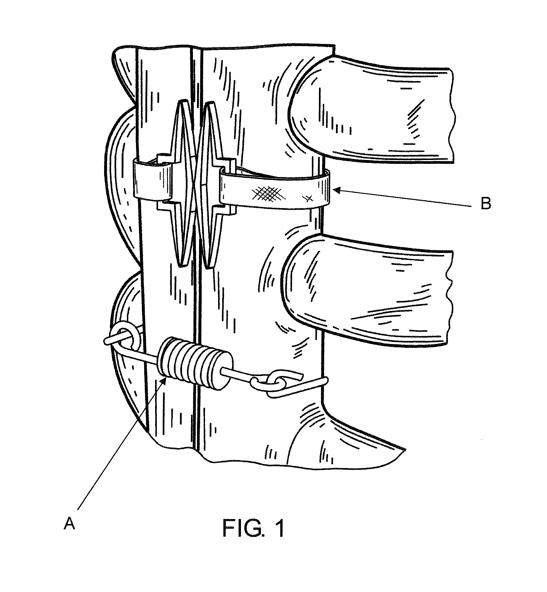
[0050]Referring now more particularly to the drawings, there is shown in FIG. 1 an example of how wires and bands might be used in binding sternal halves together for healing after open heart surgery. As noted above, two different devices are shown side by side, for comparative purposes. Device A is a prior art spring device, while Device B is an inventive device described in related application Ser. No. 12 / 406,909.

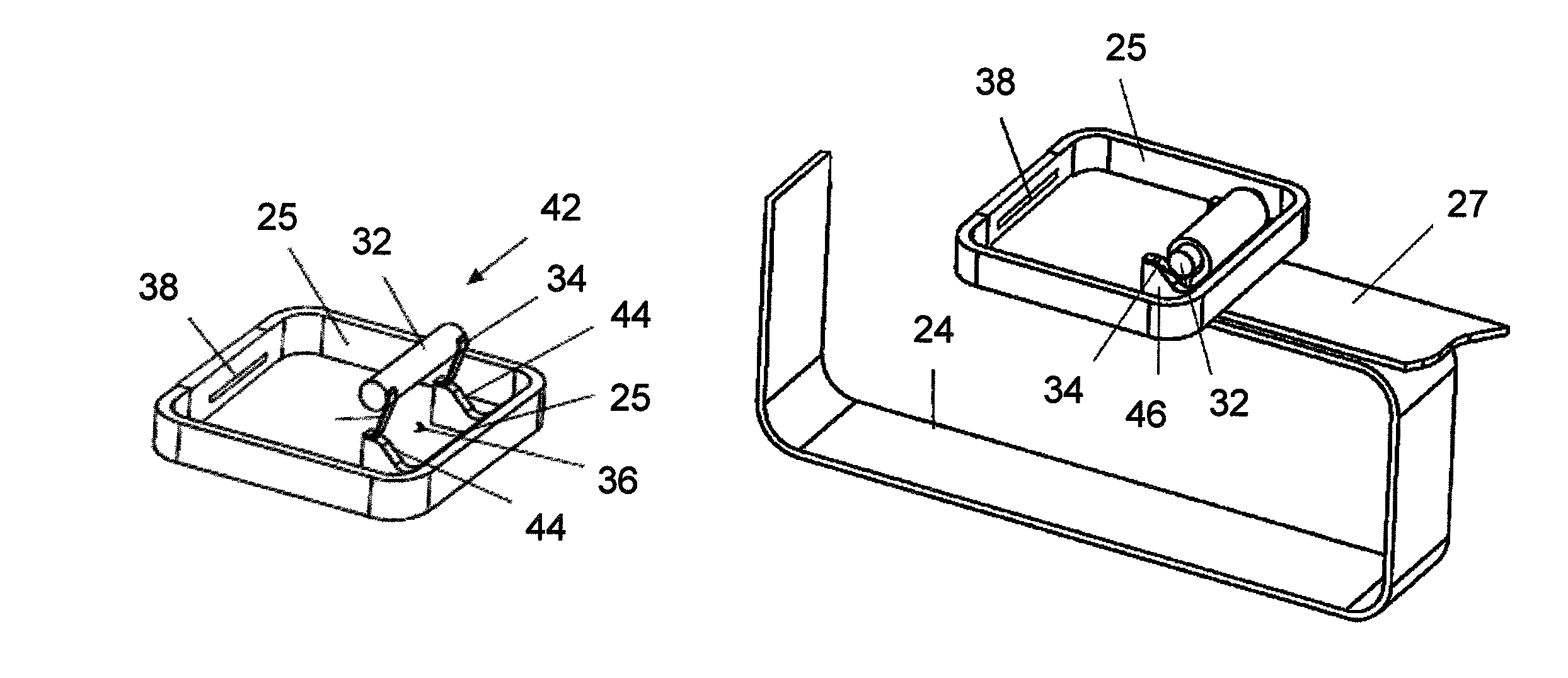
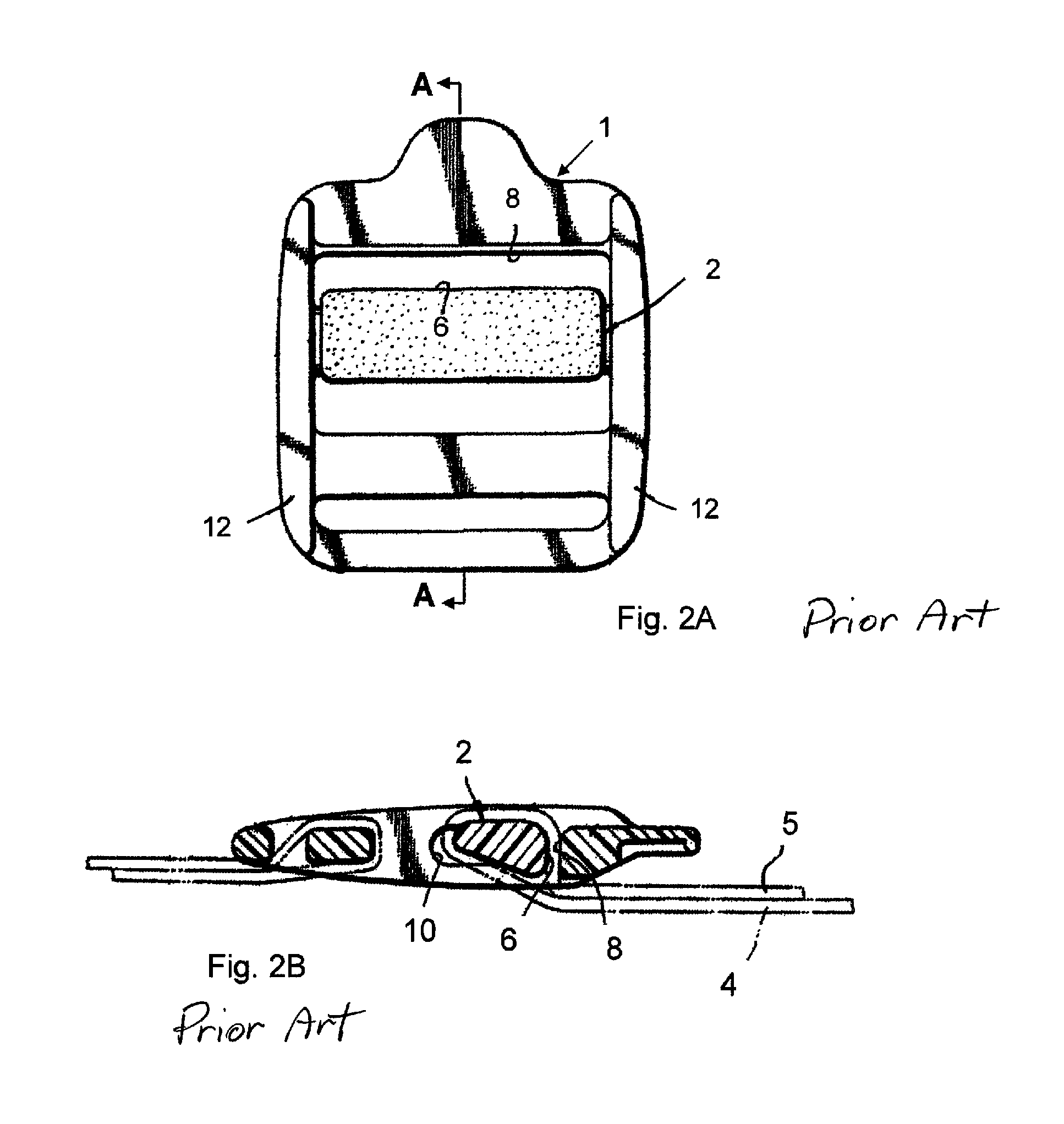
[0051]A strap locking system similar to that shown in FIG. 1, with a common buckle 1 is represented in FIGS. 2A and 2B. A common buckle 1, of a type sometimes used for straps on bags, is suitable for use in this application because of its variable tensioning abilities. Lock bar 2 moves surface 6 away from surface 8 when strap tail 5 is tensioned. As strap tail 5 is tensioned, strap tail 4 is pulled into the 6 / 8 surface interface. When strap tail 5 is released, strap tail 4 holds the dominate tension which pulls lock bar 2 so that the strap is pinched between surfaces 6 an...


PUM


Abstract

A surgical tensioning device for holding separated tissues in contact with one another. The device comprises a frame having two opposing first and second sides and a lower surface and an upper surface, and a band for extending through and around said separated tissues to be held together in conjunction with said frame. The band has two ends releasably attached to the sides of the frame. When the ends are secured to the sides of the frame, the band holds separated tissues together and establishes a path of tension along its length that extends linearly between the two ends of the band.

Description

[0001]This application claims the benefit under 35 U.S.C. 119(e) of the filing date of Provisional U.S. Application Ser. No. 61 / 225,349, entitled Flat Suture Banding System, filed on Jul. 14, 2009, and expressly incorporated herein by reference, in its entirety. This application is also related to U.S. patent application Ser. No. 12 / 347,821, entitled Dynamic Suture Tensioning Device and filed on Dec. 31, 2008, U.S. patent application Ser. No. 12 / 406,902, entitled Knotless Dynamic Suture Tensioning Device and Methods and filed on Mar. 18, 2009, U.S. patent application Ser. No. 12 / 406,904, entitled Load Shaping for Dynamic Tensioning Mechanisms and Methods and filed on Mar. 18, 2009, U.S. patent application Ser. No. 12 / 406,909, entitled Dynamic Tissue Holding Device with Low Profile Spring and filed on Mar. 18, 2009, and U.S. patent application Ser. No. 12 / 815,989, entitled Suture Band Buckle and Methods and filed on Jun. 15, 2010. All of these related applications are commonly assign...

Claims


Application Information

Patent Timeline
Patent Type & Authority Patents(United States)
IPC IPC(8): A61B17/10
CPCA61B2017/06014A61B17/823A61B17/06004A61B2017/681A61B17/10A61B17/842A61B17/82
Inventor FOERSTER, SETH ARNOLDALDRIDGE, DAVID TROTTINGWOLF
Owner ZIMMER INC
Why Eureka
Try Eureka