Processing architecture for passive optical network

Inactive Publication Date: 2014-05-06
MARVELL INT LTD
View PDF26 Cites 25 Cited by
  • Summary
  • Abstract
  • Description
  • Claims
  • Application Information

AI Technical Summary

Benefits of technology

[0007]In another embodiment, a network termination device in a passive optical network comprises a system-on-a-chip (Soc) subsystem having an SoC processor and a memory interface operatively coupled to the processor, a memory operatively coupled to the memory interface, and an integrated chip having a distributed direct memory access engine operatively coupled to the SoC processor and the memory interface to interconnect the integrated circuit with the SoC sub-system and to directly access the memory. The distributed direct memory access engine includes a system-on-a-chip (SoC) interface, a first direct memory access engine operatively coupled to the SoC interface to read data from the memory, and a second direct memory access engine operatively coupled to the SoC interface to write data to the memory. In some of these embodiments, the distributed direct memory access engine further includes a descriptor and buffer management unit operatively coupled to the first direct memory access engine and adapted to manage access of the first direct memory access engine to the memory; and a memory management unit operatively coupled to the second direct memory access engine and adapted to manage access of the second direct memory access engine to the memory. In some embodiments, the integrated chip further includes a transmitter operatively coupled to the first direct memory access engine, a receiver operatively coupled to the second direct memory access engine and an internal processor operatively coupled to the transmitter and the receiver, wherein the internal processor is adapted to control the integrated chip and to execute functions requiring execution within a minimum timeframe, and wherein the SoC processor is adapted to execute functions that do not require execution within the minimum timeframe, wherein the internal processor is adapted to process a transmission header associated with a transmission and the SoC processor is adapted to process a data packet associated with the transmission.

Problems solved by technology

Whereas, on the other hand, if non-time sensitive functions were added to the functionality of an architecture otherwise responsible for time-sensitive functions unnecessary delay and jitter could result.

Method used


Image

  • Processing architecture for passive optical network
  • Processing architecture for passive optical network
  • Processing architecture for passive optical network

Examples


Embodiment Construction

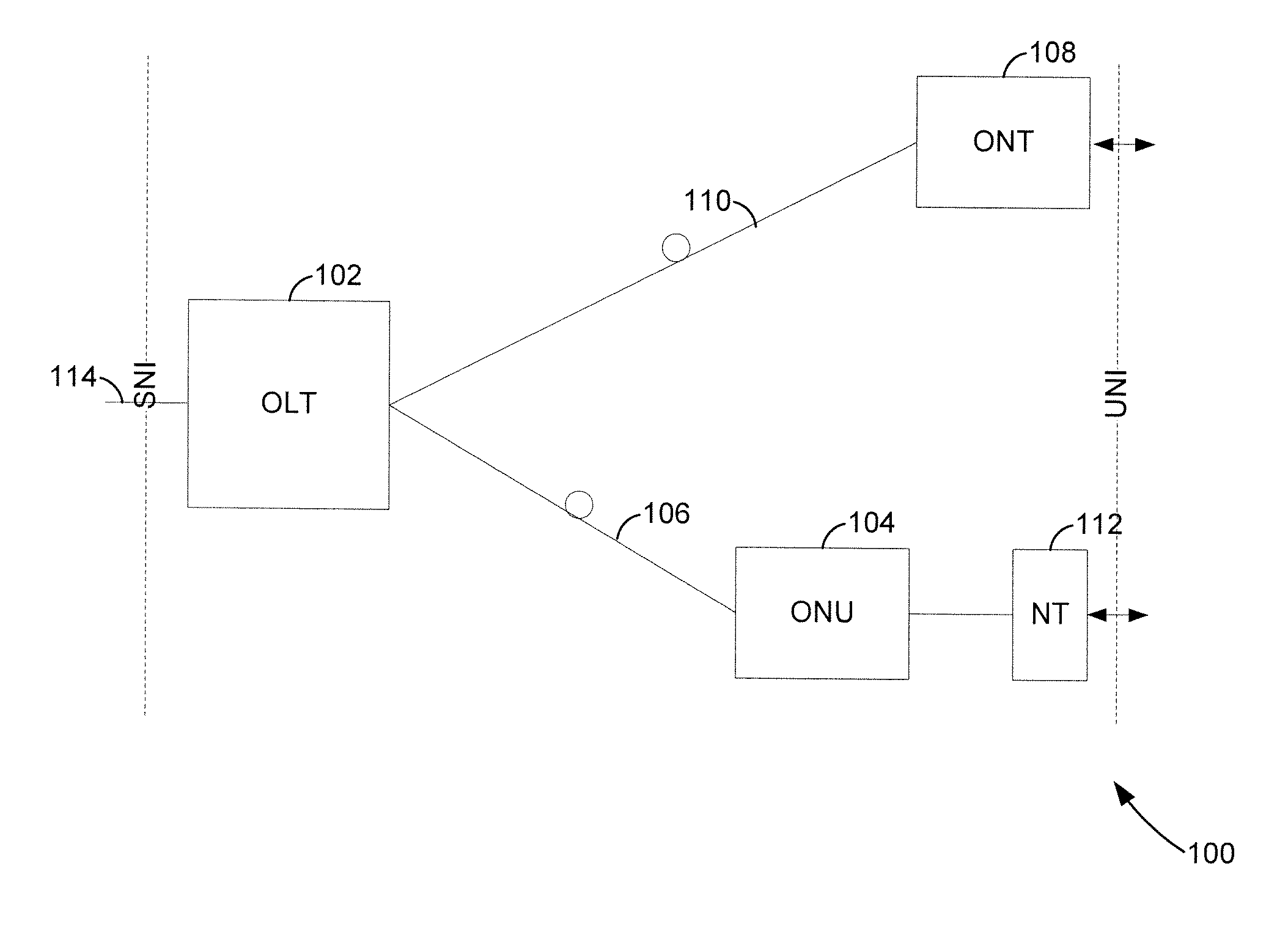
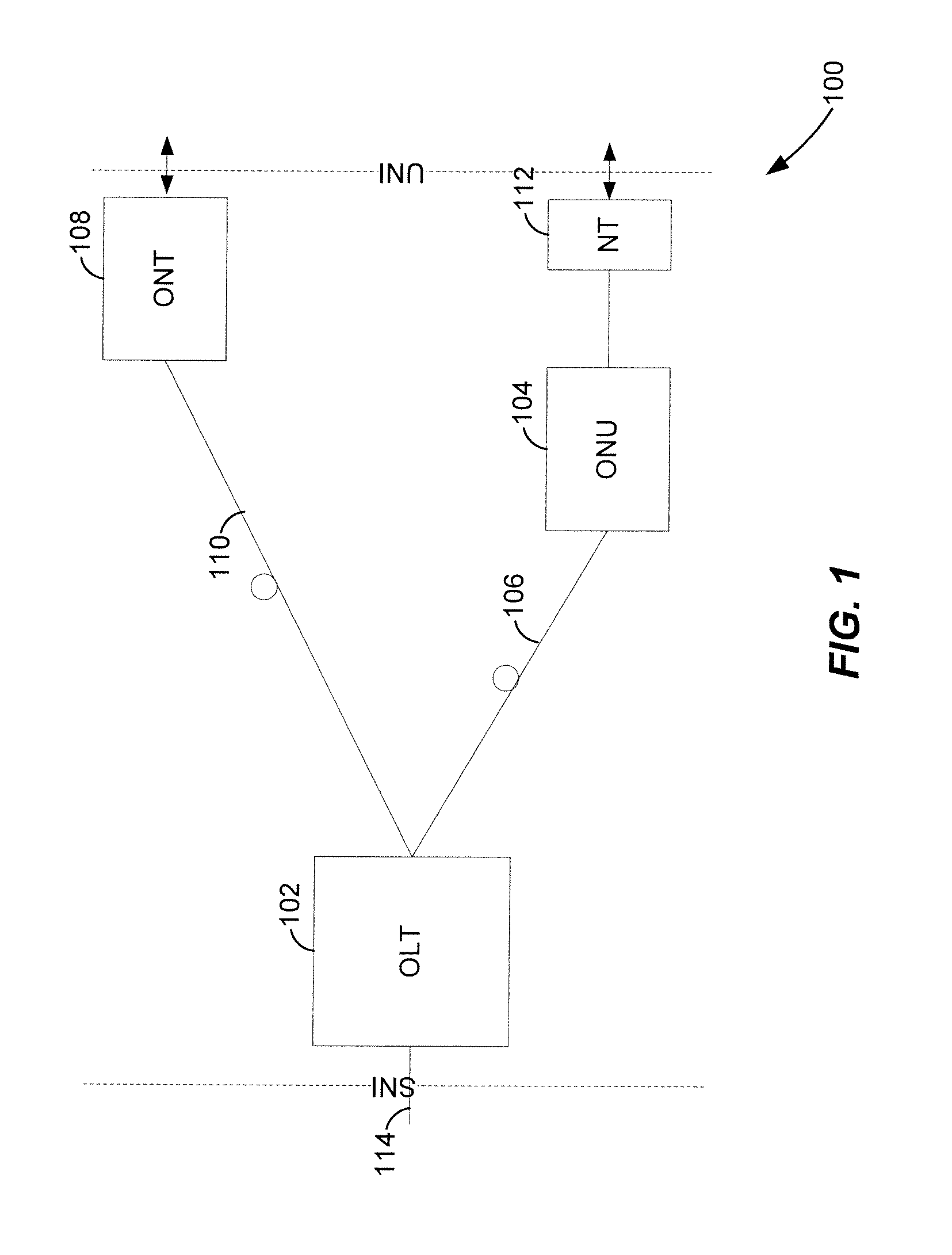
[0016]FIG. 1 shows an example GPON configuration 100 with an OLT 102 communicatively coupled to a backbone network as a service node interface (SNI) such as at a provider of interne services, television services, telephony services, or other network services provider. Typical backbone interfaces include time division multiplexed (TDM) interfaces, such as SONET / SDH or PDH, and Gigabit and 100 Mbit / s Ethernets. The OLT 102 is communicatively coupled to an ONU 104 through optical fiber 106 and to an ONT 108 through another optical fiber 110, with both the ONT 108 and the ONU 104 being at a user network interface end of the configuration 100. The ONU 104 and the ONT 108 may operate under an ATM mode, GPON encapsulation method (GEM) mode, or Dual mode, in typical examples. While this disclosure refers to both ONUs (e.g., 104) and ONTs (e.g., 108), it should be understood that in the context of this disclosure, ONTs and ONUs may be treated similarly and these terms may be considered inter...


PUM


Abstract

In a network termination device integrated circuit in a point-to-multipoint network, a receiver receives a downstream transmission from a line termination unit within the point-to-multipoint network, a transmitter transmits an upstream transmission to the line termination unit within the point-to-multipoint network, and an internal processor operatively coupled to the receiver processes sub-fields within the overhead field of the downstream transmission. The internal processor is also operatively coupled to the transmitter to assemble the overhead field of the upstream transmission. The downstream transmission is an downstream transmission convergence frame format having an overhead field and a payload field, and the upstream transmission is an upstream transmission convergence frame format having an overhead field and a payload field.

Description

CROSS-REFERENCES TO RELATED APPLICATIONS[0001]The present application claims the benefit of U.S. Provisional Application No. 60 / 862,665, entitled “GPON SOLUTION ARCHITECTURE,” filed on Oct. 24, 2006, which is hereby incorporated by reference herein in its entirety.FIELD OF TECHNOLOGY[0002]The present disclosure relates generally to point-to-multipoint networks, and more particularly, to network termination devices in a gigabit passive optical network.DESCRIPTION OF THE RELATED ART[0003]Point-to-multipoint networks such as passive optical networks (PONs) provide efficient communications (voice, data, telephony, etc.) without substantial power consumption. A typical PON for example includes an optical line termination (OLT) acting as a network-side broadcast point that communicates with multiple optical network units (ONUs) and / or optical network terminations (ONTs) on the user side of the network. An optical fiber or bundle creates the connection between the OLT and the many ONTs / ONU...

Claims


Application Information

Patent Timeline
Patent Type & Authority Patents(United States)
IPC IPC(8): H04L12/66
CPCH04L12/12Y02B60/34H04L12/66Y02D30/50
Inventor JOHNSTON, CESAR A.CHIANG, JOHN M.
Owner MARVELL INT LTD
Why Eureka
Try Eureka