Phase grating used for X-ray phase imaging, imaging apparatus for X-ray phase contrast image using phase grating, and X-ray computed tomography system

a phase grating and imaging apparatus technology, applied in the field of phase grating used for xray phase imaging, can solve the problems of difficult to make phase grating b>21/b>, inability to achieve enough contrast for biological soft tissue and soft material, and difficult to make diffraction grating with a large area

Inactive Publication Date: 2014-05-06
CANON KK
View PDF26 Cites 9 Cited by
  • Summary
  • Abstract
  • Description
  • Claims
  • Application Information

AI Technical Summary

Benefits of technology

[0010]According to the present invention, it is possible to realize the phase grating used for the X-ray phase imaging in which the pitch can be narrowed by using the diffraction grating with the low aspect. Further, according to the present invention, it is possible to realize the imaging apparatus for the X-ray phase contrast image, in which the above phase grating is used, and the X-ray computed tomography system including the imaging apparatus.

Problems solved by technology

However, as an element becomes lighter, the X-ray absorption ability becomes smaller, resulting in a problem that enough contrast cannot be expected for biological soft tissue and soft material.
Thus, such a problem is induced that an aspect ratio becomes larger, which is defined by the thickness (height) of the projection part / the aperture width of the aperture part, or the thickness (height) of the projection part / the width of the projection part, so that it becomes difficult to make the phase grating 21.
In this case, the aspect ratio becomes approximately 30, resulting in that it is difficult to make the diffraction grating with a large area.

Method used


Image

  • Phase grating used for X-ray phase imaging, imaging apparatus for X-ray phase contrast image using phase grating, and X-ray computed tomography system
  • Phase grating used for X-ray phase imaging, imaging apparatus for X-ray phase contrast image using phase grating, and X-ray computed tomography system
  • Phase grating used for X-ray phase imaging, imaging apparatus for X-ray phase contrast image using phase grating, and X-ray computed tomography system

Examples


exemplary embodiment 1

(Exemplary Embodiment 1)

[0037]An example of the phase grating according to the present invention will be described below.

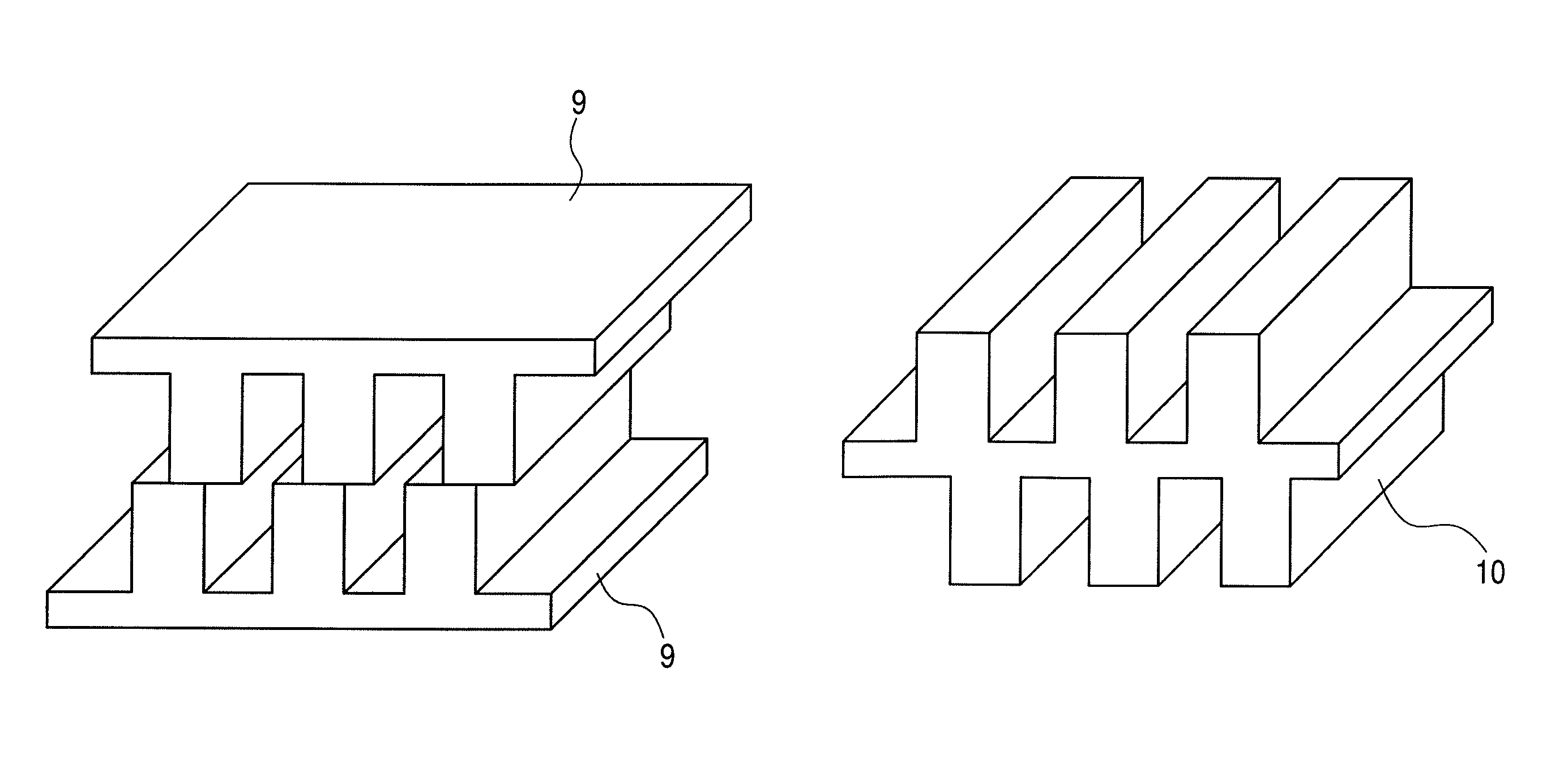
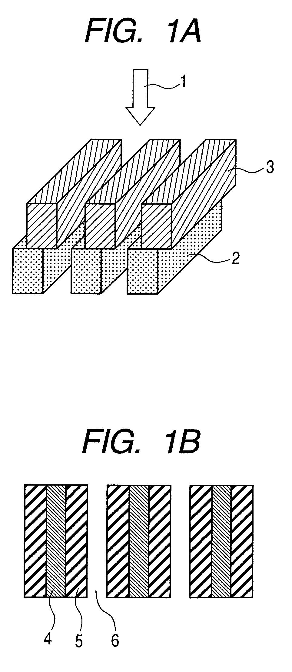
[0038]In the exemplary embodiment 1, an exemplary configuration of a one-dimensional phase grating will be described, which is used for X-ray phase imaging with a structure in which a pitch is narrowed than each diffraction grating by stacking two layers of line-like diffraction gratings displayed in a cyclic direction for an in-coming X-ray. FIG. 1A illustrates the exemplary configuration of the one-dimensional phase grating in which a first diffraction grating 2 and a second diffraction grating 3 are displaced with respect to each other and stacked upon each other. In the one-dimensional phase grating of the present exemplary embodiment, the line-like diffraction grating means a structure in which line-like projection structures (projection parts) which are parallel to each other, and aperture parts with the same aperture width as a width of the projection part ...

exemplary embodiment 2

(Exemplary Embodiment 2)

[0046]In the embodiment 2, an exemplary configuration of a two-dimensional phase grating, in which a stacking direction is different from that of the above exemplary embodiment 1, will be described. FIG. 4A illustrates a view for describing an exemplary configuration of the two-dimensional phase grating in the present exemplary embodiment.

[0047]The two-dimensional phase grating according to the present exemplary embodiment is formed as stacked so that a cyclic direction of a first layer of a diffraction grating 2 (a first diffraction grating), and a cyclic direction of a second layer of a diffraction grating 3 (a second diffraction grating) are orthogonal to each other. The first and second diffraction gratings are structured so that the projection part whose thickness is formed so that the in-coming X-ray transmits with the phase π-shifted, and the aperture part with the same aperture width as a width of projection part are cyclically arranged, and the width...

exemplary embodiment 3

(Exemplary Embodiment 3)

[0050]In the exemplary embodiment 3, an exemplary configuration of the phase grating used for the X-ray phase imaging, in which three or more layers of the diffraction gratings are stacked to be multilayered, will be described. FIG. 7A illustrates the phase grating used for the X-ray phase imaging, which is configured with the three layers of the diffraction gratings, in the present exemplary embodiment.

[0051]The phase grating according to the present exemplary embodiment is configured so that such diffraction gratings are stacked as displaced by ⅙-pitch in the cyclic direction for the diffraction grating of the lower layer. For example, the phase grating is configured by stacking the second layer of the diffraction grating displaced by ⅙-pitch, and the third layer of the diffraction grating 17 further displaced by ⅙-pitch for the first layer of the diffraction grating 2. The structure of each diffraction grating is constructed in a manner that the projection...


PUM


Abstract

A phase grating used for X-ray phase imaging is provided, in which a pitch can be narrowed by using a diffraction grating with a low aspect ratio. A phase grating used for X-ray phase imaging, characterized in that the phase grating includes a first diffraction grating in which a first projection part whose thickness is formed so that an in-coming X-ray transmits with a phase π-shifted, and a first aperture part with the same aperture width as a width of the first projection part are cyclically arranged, and a second diffraction grating in which a second projection part with the same width as a width of the first projection part, and a second aperture part with the same aperture width as the aperture width of the first aperture part are cyclically arranged, and the second diffraction grating is formed as displaced on the first diffraction grating.

Description

CROSS REFERENCE TO RELATED APPLCIATIONS[0001]This application is a U.S. National Stage of International application No. PCT / JP2009 / 055375 filed on Mar. 12, 2009 which claims priority from Japanese Patent Application No. 2008-064709 filed on Mar. 13, 2008, the disclosures of which are hereby incorporated by reference herein in their entirety.TECHNICAL FIELD[0002]The present invention relates to a phase grating used for X-ray phase imaging, an imaging apparatus for an X-ray phase contrast image using the phase grating, and an X-ray computed tomography system.BACKGROUND ART[0003]Conventionally, an X-ray fluoroscopic imaging technique has been studied, which obtains a contrast image by utilizing the difference of X-ray absorption abilities. However, as an element becomes lighter, the X-ray absorption ability becomes smaller, resulting in a problem that enough contrast cannot be expected for biological soft tissue and soft material. In view of above mentioned problem, an imaging method w...

Claims


Application Information

Patent Timeline
Patent Type & Authority Patents(United States)
IPC IPC(8): G21K1/00
CPCA61B6/484G21K2207/005G02B5/1814G02B5/1871G21K1/06A61B6/4291A61B6/06
Inventor NAKAMURA, TAKASHIIMADA, AYAITOH, HIDENOSUKE
Owner CANON KK
Why Eureka
Try Eureka