Laminated core punching apparatus

a core punching and laminating technology, applied in the direction of printing machines, instruments, manufacturing stator/rotor bodies, etc., can solve the problems of rotor punching, accumulator that is required when two, and the running condition of strip-form steel plates is more likely to become unstable, so as to prevent loop inverting, increase line speed dramatically, and large

Active Publication Date: 2014-05-13
NORITSU KIKAI SEISAKUSHO
View PDF14 Cites 3 Cited by
  • Summary
  • Abstract
  • Description
  • Claims
  • Application Information

AI Technical Summary

Benefits of technology

[0008]In a laminated core punching apparatus including the accumulator described above, the length of the strip-form steel plate that has to be stored during a stoppage increases steadily with increases in the punching speed, and as a result, the size of the accumulator must be increased even further. Moreover, when the speed of the strip-form steel plate passing through the accumulator and at the front and rear thereof is increased, a running condition of the strip-form steel plate is more likely to become unstable. It is therefore desirable to develop a laminated core punching apparatus in which the punching speed can be increased without the use of an accumulator.
[0009]To improve the efficiency of a press machine, the number of stopping operations performed by the press machine must be reduced. This can be achieved using various methods, and performing a core lamination process in two stations, as proposed by Japanese Patent Application Publication JP-A-S58-108948, for example, is effective.
[0010]However, although the method proposed in Japanese Patent Application Publication JP-A-S58-108948 is effective for improving the efficiency of a single press apparatus, namely the rotor-punching press machine or the stator-punching press machine, the accumulator that is required when two press machines, i.e. the rotor-punching press machine and the stator-punching press machine, are arranged in series cannot simply be eliminated.

Problems solved by technology

Moreover, when the speed of the strip-form steel plate passing through the accumulator and at the front and rear thereof is increased, a running condition of the strip-form steel plate is more likely to become unstable.
However, although the method proposed in Japanese Patent Application Publication JP-A-S58-108948 is effective for improving the efficiency of a single press apparatus, namely the rotor-punching press machine or the stator-punching press machine, the accumulator that is required when two press machines, i.e. the rotor-punching press machine and the stator-punching press machine, are arranged in series cannot simply be eliminated.

Method used


Image

  • Laminated core punching apparatus
  • Laminated core punching apparatus
  • Laminated core punching apparatus

Examples


first embodiment

[0037](First Embodiment)

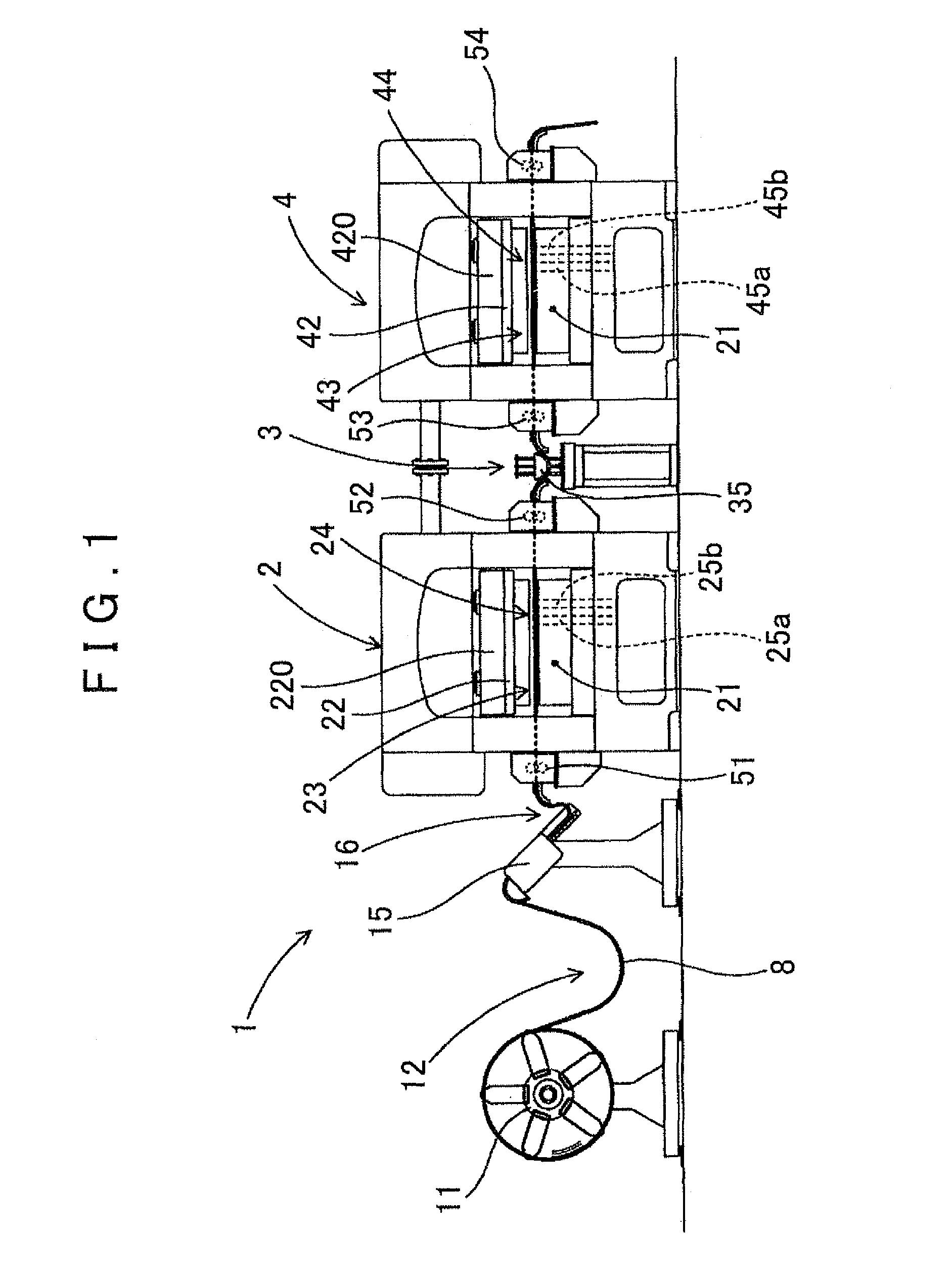
[0038]A laminated core punching apparatus according to an embodiment of the present invention will now be described using FIGS. 1 to 11.

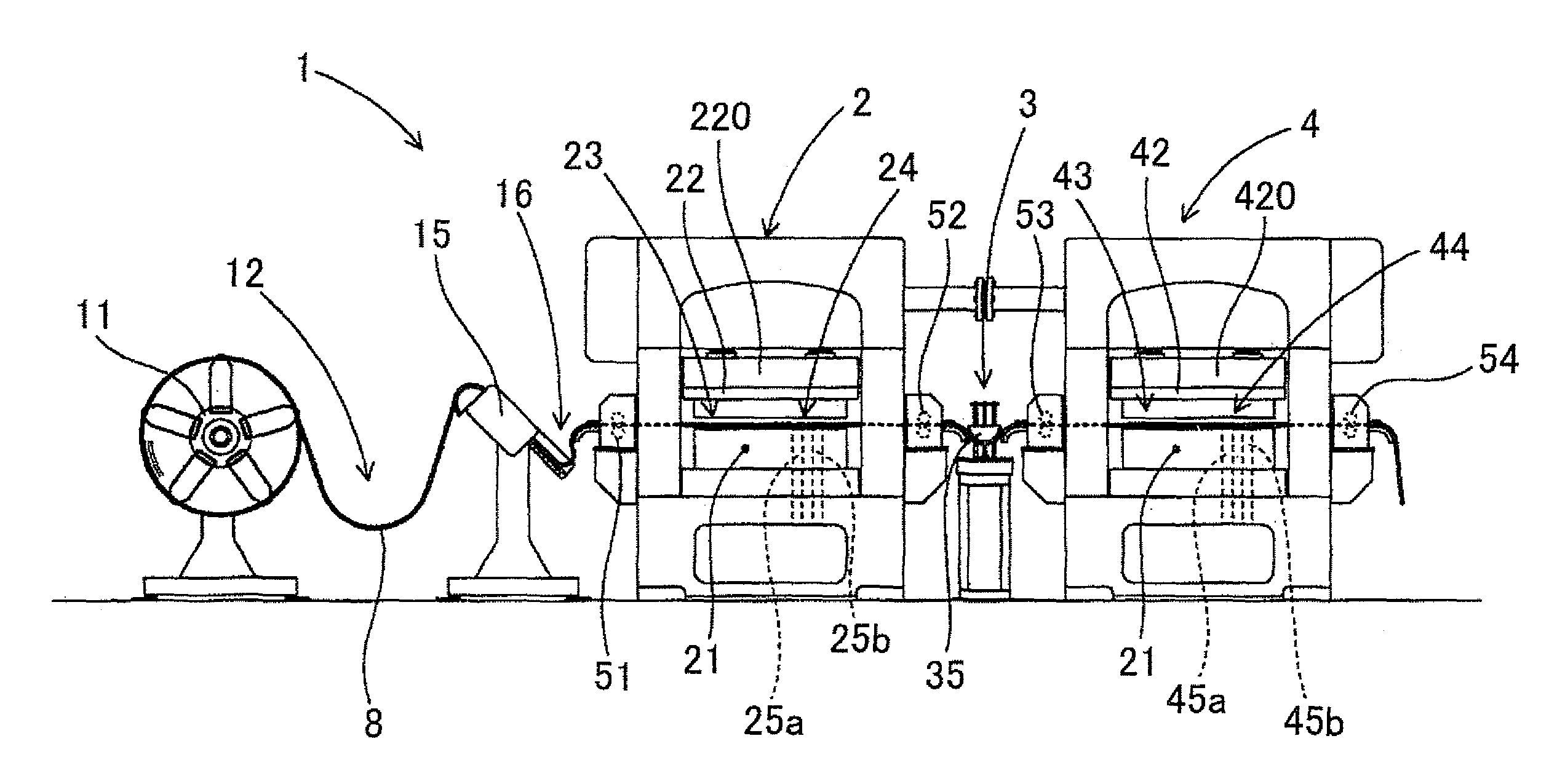
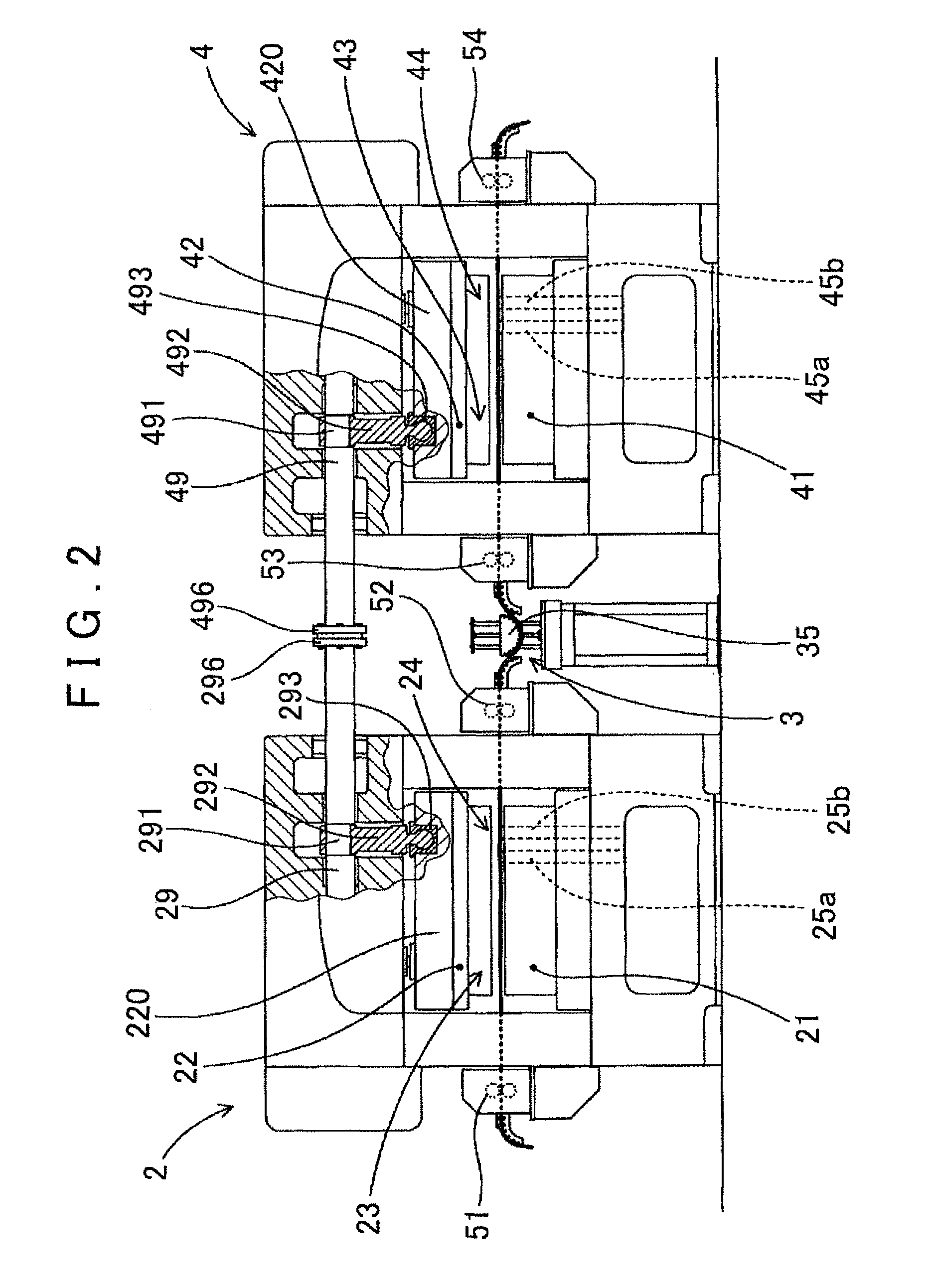
[0039]As shown in FIG. 1, a laminated core punching apparatus 1 according to this embodiment includes an uncoiler 11 for unwinding a strip-form steel plate 8 for an iron core that is wound into a coil shape and set thereon, a rotor-punching press machine 2 for punching out a rotor core piece 81 (FIG. 3) from the strip-form steel plate 8 and laminating the punched rotor core piece 81, and a stator-punching press machine 4 for punching out a stator core piece 82 (FIG. 4) from the strip-form steel plate 8 following punching of the rotor core piece 81 and laminating the punched stator core piece 82.

[0040]The rotor-punching press machine 2 includes a molding die 23 that performs partial punching gradually to approach the shape of the rotor core piece 81, a punching die 24 for punching out the rotor core piece 81 from the strip-for...


PUM

PropertyMeasurementUnit
outer diameteraaaaaaaaaa
rotation angleaaaaaaaaaa

Abstract

A laminated core punching apparatus, configured such that a stator-punching press machine that has a molding die performing a partial punching gradually approaches the shape of the stator core piece. There is a punching die to punching out the stator core piece from a strip-form steel plate, and two stator lamination stations. A rotor-punching press machine and a stator-punching press machine are constructed to operate synchronously. An intermediate loop portion capable of causing a strip-form steel plate to hang down in a loop is provided in order to adjust a length of the strip-form steel plate between the two press machines, and a loop guide portion that guides a loop locus of the strip-form steel plate from above so that the strip-form steel plate does not invert is disposed above the intermediate loop portion to be capable of ascending and descending.

Description

INCORPORATION BY REFERENCE[0001]The disclosure of Japanese Patent Application No. 2010-072477 filed on Mar. 26, 2010 including the specification, drawings and abstract is incorporated herein by reference in its entirety.BACKGROUND OF THE INVENTION[0002]The present invention relates to a laminated core punching apparatus for forming a rotor laminated body and a stator laminated body by punching out rotor core pieces and stator core pieces, which serve as a rotor core and a stator core for a rotating electrical machine such as a motor, from a strip-form steel plate and laminating the punched pieces.DESCRIPTION OF THE RELATED ART[0003]Recent years have seen an increase in demand for comparatively large motors that can be used in hybrid vehicles, electric vehicles, and so on. In a rotating electrical machine such as a motor, a laminated core formed by laminating steel plates is used. The laminated core is typically manufactured by punching a strip-form steel plate serving as a raw mater...

Claims


Application Information

Patent Timeline
Patent Type & Authority Patents(United States)
IPC IPC(8): H02K15/02B21D28/02B23P21/00B21D28/06
CPCH02K15/02B21D28/06H02K15/022B21D28/02H02K15/024B23P21/004Y10T29/5317Y10T29/5136Y10T29/5197Y10T29/53165Y10T29/53161Y10T29/5138Y10T29/5192
Inventor MATSUBARA, TETSUYAMAEDA, SHIGERUTAKAGI, ATSUYAOOURA, TAKUYANISHIGUCHI, HAJIMEKOORI, MOTOKIHAYABUCHI, MASAHIROKATO, SUSUMUOHKI, KEISHISHINOHARA, KENJIMURAKAMI, AKIO
Owner NORITSU KIKAI SEISAKUSHO
Why Eureka
Try Eureka