Punching machine

A punching machine and punching technology, applied in the direction of metal processing, etc., to achieve the effect of simple structure, convenient installation and easy replacement

Active Publication Date: 2012-06-27
NINGBO SUPREME ELECTRONIC MASCH INC
View PDF6 Cites 4 Cited by
  • Summary
  • Abstract
  • Description
  • Claims
  • Application Information

AI Technical Summary

Problems solved by technology

[0003] The technical problem to be solved by the present invention is to provide a punching machine aiming at the above-mentioned current state of the art, which overcomes the technical problems that the punching device in the prior art cannot punch holes quickly and efficiently, and cannot accurately locate the punching position

Method used


Image

  • Punching machine
  • Punching machine
  • Punching machine

Examples


Embodiment Construction

[0025] Embodiments of the present invention will be described in further detail below in conjunction with the accompanying drawings.

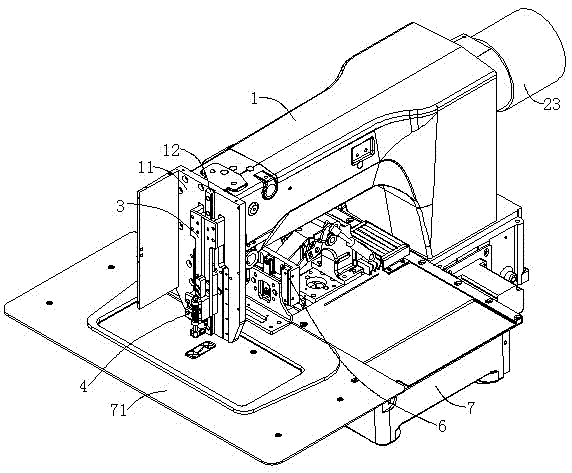
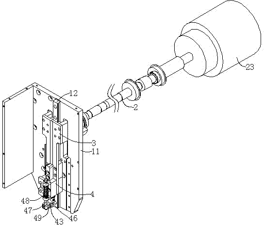
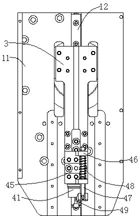
[0026] Figure 1 to Figure 9 Shown is the structural representation of the present invention.

[0027] The reference signs therein are: machine head 1, fixed seat 11, chute 11a, longitudinal guide rail 12, longitudinal slider 13, punching knife slide rail 14, punching knife slider 15, main shaft 2, eccentric wheel 21, eccentric rotating shaft 21a , crank 22, driving motor 23, power output shaft 24, longitudinal transmission base 3, front plate 3a, connecting shaft 3b, rear plate 3c, punching knife 4, knife rest 41, punching knife head 43, presser foot base 45, Presser foot bracket 46, presser foot rod 47, return spring 48, presser foot 49, punch hole 49a, feeding mechanism 6, base 61, feeding plate 62, pressing plate 63, driving arm 64, pressing plate guide rail 65, pressing plate slide Block 66, drive cylinder 67, link mechanism 68, machine ...


PUM


Abstract

The invention discloses a punching machine, which comprises a main shaft which is arranged in a handpiece and driven by a driving motor to rotate, a longitudinal transmission base which is arranged in the handpiece in a sliding manner and driven by the main shaft through a transmission mechanism to do up-and-down motion, a punching cutter which is fixedly arranged on the longitudinal transmissionbase and used for punching a material, a workbench which is arranged below the handpiece and used for holding the material, and a material conveying mechanism which is arranged on the workbench and used for clamping the material, wherein the material conveying mechanism can do feeding motion in the horizontal X direction and the horizontal Y direction under the driving of a material conveying driving mechanism and can convey a punching part of the material to a position below the punching cutter; and under the driving of the driving motor, the longitudinal transmission base drives the punching cutter to move downwards and punch the material.

Description

technical field [0001] The invention relates to a punching machine for punching holes in thin materials. Background technique [0002] In industrial production, it is often necessary to punch thin materials such as cloth and plastic films. Invention patent name: A non-woven fabric punching and forming device, patent application number: 201010202137.7 discloses a non-woven fabric punching and forming device, which includes a pneumatic punching device, a knife die device, an electric transmission device and a motor box, Pneumatic stamping device is arranged on the upper part of the device, die cutting device is connected to the lower part of the pneumatic stamping device, the die cutting device is supported and connected on the top platform of the motor box, and the electric transmission device is arranged on the top of the motor case. The non-woven fabric punching and forming device disclosed in this patent adopts a pneumatic punching device, so the punching efficiency is lo...

Claims


Application Information

Patent Timeline
Patent Type & Authority Applications(China)
IPC IPC(8): B26F1/02B26D7/06B26D7/02B26D5/08
Inventor 罗千邹宗敏陈初喜
Owner NINGBO SUPREME ELECTRONIC MASCH INC
Why Eureka
Try Eureka