Ankle stabilizing apparatus having a dynamic cuff and stabilizing strap system

a dynamic cuff and stabilizing strap technology, applied in the field of ankle stabilizing equipment, can solve the problems of reducing so as to improve the stability of the ankle and foot, prevent sprains, and increase the amount of tension

Active Publication Date: 2014-05-13
MEDICAL SPECIALTIES
View PDF15 Cites 17 Cited by
  • Summary
  • Abstract
  • Description
  • Claims
  • Application Information

AI Technical Summary

Benefits of technology

[0008]In one embodiment, one end of the stabilizing strap is positioned against an interior surface of a lower portion of the body member. Advantageously, the cuff member serves as an anchor for the pulley-like effect as the stabilizing strap passes through the slots in the cuff member. As the foot and ankle rotate (i.e., eversion or inversion) during use, a portion of the stabilizing strap positioned against an exterior surface of the body member is drawn tighter. The tightening of this portion of the stabilizing strap transmits an increased amount of tension to the portion of the stabilizing strap positioned against the interior surface of the body member (i.e., the stirrup portion of the strap that passes under the heel). The increased tension on the stabilizing strap applies compression against the body member and ankle to thereby stabilize the ankle and foot, and prevent a sprain. Thus, the apparatus dynamically responds to the movement of the ankle and body member during use and provides increased stability.
[0009]The stabilizing strap may include grip-enhancing fabric in the heel area adjacent to the foot to thereby transfer the tensioning force against the foot. Tensioning of the stabilizing strap during application and use promotes grip and secures the heel to reduce the amount of foot and ankle rotation, and thereby reduce tendon strain (e.g., an ankle sprain).
[0010]In one embodiment illustrated in FIG. 10, the angled slots in the cuff member create X and Y axis components of force when the strap is tensioned (i.e., FX and FY, respectively). The combination of the X and Y force components results in a resultant force (i.e., FR). The FX force component acting on the stabilizing strap varies the tension in the cuff of the apparatus. Tension in the cuff is caused by tension applied by portions of the stabilizing strap positioned against exterior surfaces of the body member. Specifically, the FX force component results in cylindrical tightening of the cuff (i.e., compression) which aids in the reduction of the high-ankle sprain injury known as syndesmosis. The cuff of the apparatus is dynamic in the sense that the cuff member promotes increased compression when the stabilizing strap is tightened both during application and when the apparatus actively restricts ankle rotation (i.e., during use). As configured, the dynamic tightening of the cuff minimizes the effects of syndesmosis by applying increased compression the moment the foot is under load and rotates excessively.
[0011]The FY force component acting on the stabilizing strap varies the tension in an interior stirrup region of the body member. Thus, the user may adjust tension applied by portions of the stabilizing strap positioned against an interior surface of the body member after securely lacing the boot. This configuration simultaneously allows the tensioning of the strap portions positioned against interior surfaces of the body member (i.e., stirrup region) and the strap portions positioned against exterior surfaces of the body member (i.e., portions as applied in an overlying FIG. 8 pattern about the body member). Advantageously, the resultant force (FR) or FR force component provides the simultaneous tensioning of the strap portions positioned against the interior and exterior surfaces of the body member.
[0013]The dynamic cuff and stabilizing strap system of the present ankle apparatus comfortably and effectively addresses the issue of distal migration through the aforementioned variable compression (which increases with increased foot rotation) and by introducing an inverted, truncated cone shape which mirrors the anatomy of the typical lower leg. The inverted, truncated cone shape of the cuff of the body member is accomplished by introducing variable thickness in the vertical direction to the cuff enclosure. This is accomplished by incorporating a strip of material (e.g., fabric) or a flexible sheet member on the interior surface of the cuff enclosure as applied against the cuff member and interior surface of the body member. The flexible sheet member may partially cover the inferior or lower portion of the cuff enclosure. The application of the flexible sheet member to the cuff enclosure results in an increased circumference of the lower cuff which is substantially adjacent to the leg at its minimum thickness just above the malleolli of the ankle. In one embodiment, the thickness of the cuff is approximately 33% greater near the lower edge of the cuff member where the lower leg and ankle are narrower. This configuration permits an outermost binding strap—which may cover the cuff as the final step in application—to compress the cuff across a greater area in a more uniform fashion because the exterior surface of the cuff defines a more geometrically accurate cylindrical shape.

Problems solved by technology

As known to participants in athletics, the ankle is often injured as a result of contact with other participants or equipment, or as a result of the ankle assuming an unnatural position during play.
Specifically, ankles are particularly vulnerable to sprains, fractures, and the like.
For example, taping may restrict all motion of the ankle, both desirable and undesirable, because the tape is wound circumferentially around the ankle.
The restrictive characteristics of taping thus hinder the athlete's ability to perform.
Further, tape tends to stretch and loosen as the athlete moves, thereby decreasing its effectiveness in supporting the ankle.
Moreover, undesirable movement of the ankle may occur as a result of lateral or vertical movement of upper portions of the body member relative to lower portions of the body member.

Method used


Image

  • Ankle stabilizing apparatus having a dynamic cuff and stabilizing strap system
  • Ankle stabilizing apparatus having a dynamic cuff and stabilizing strap system
  • Ankle stabilizing apparatus having a dynamic cuff and stabilizing strap system

Examples


Embodiment Construction

[0026]The present invention will now be described more fully hereinafter with reference to the accompanying drawings, in which a preferred embodiment of the invention is shown. This invention may, however, be embodied in many different forms and should not be construed as limited to the embodiments set forth herein. Rather, these embodiments are provided so that this disclosure will be thorough and complete, and will fully convey the scope of the invention to those skilled in the art. Like numbers refer to like elements throughout.

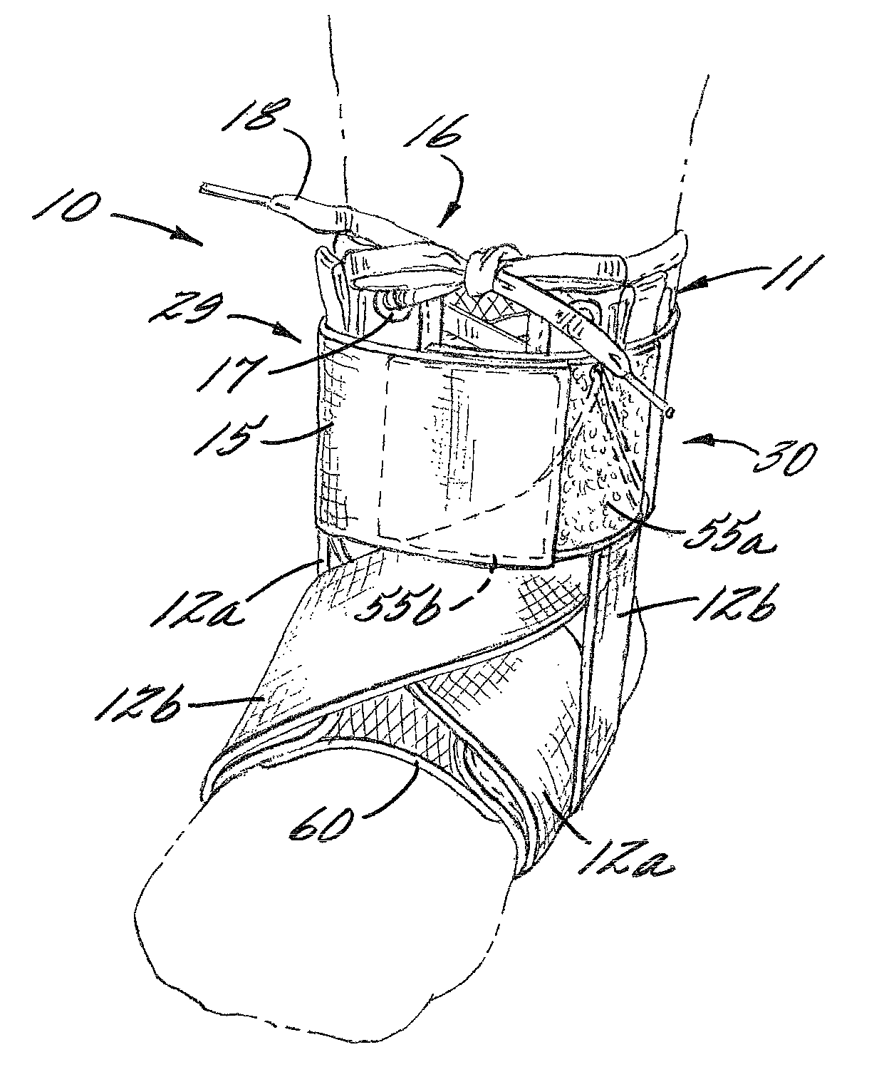
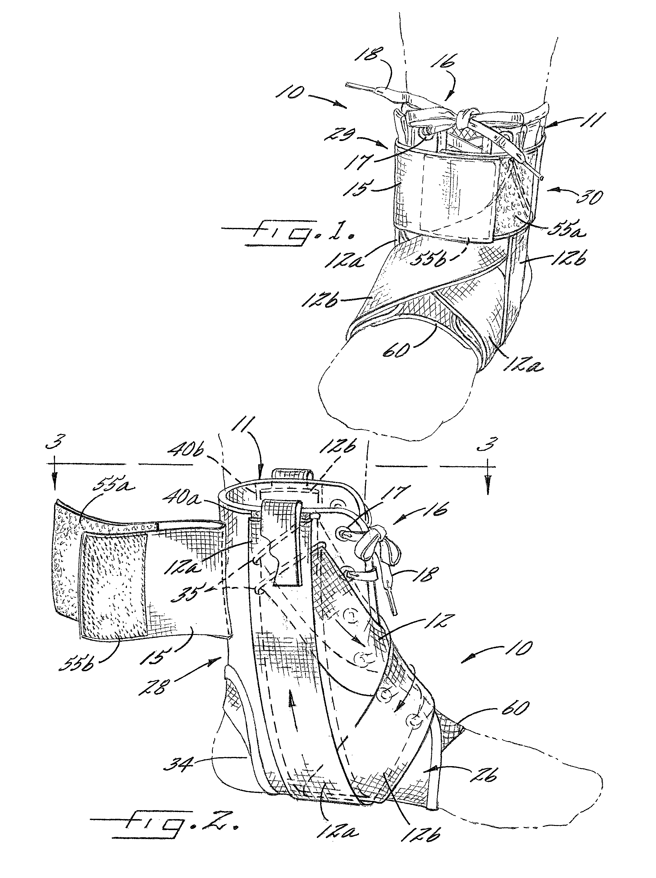
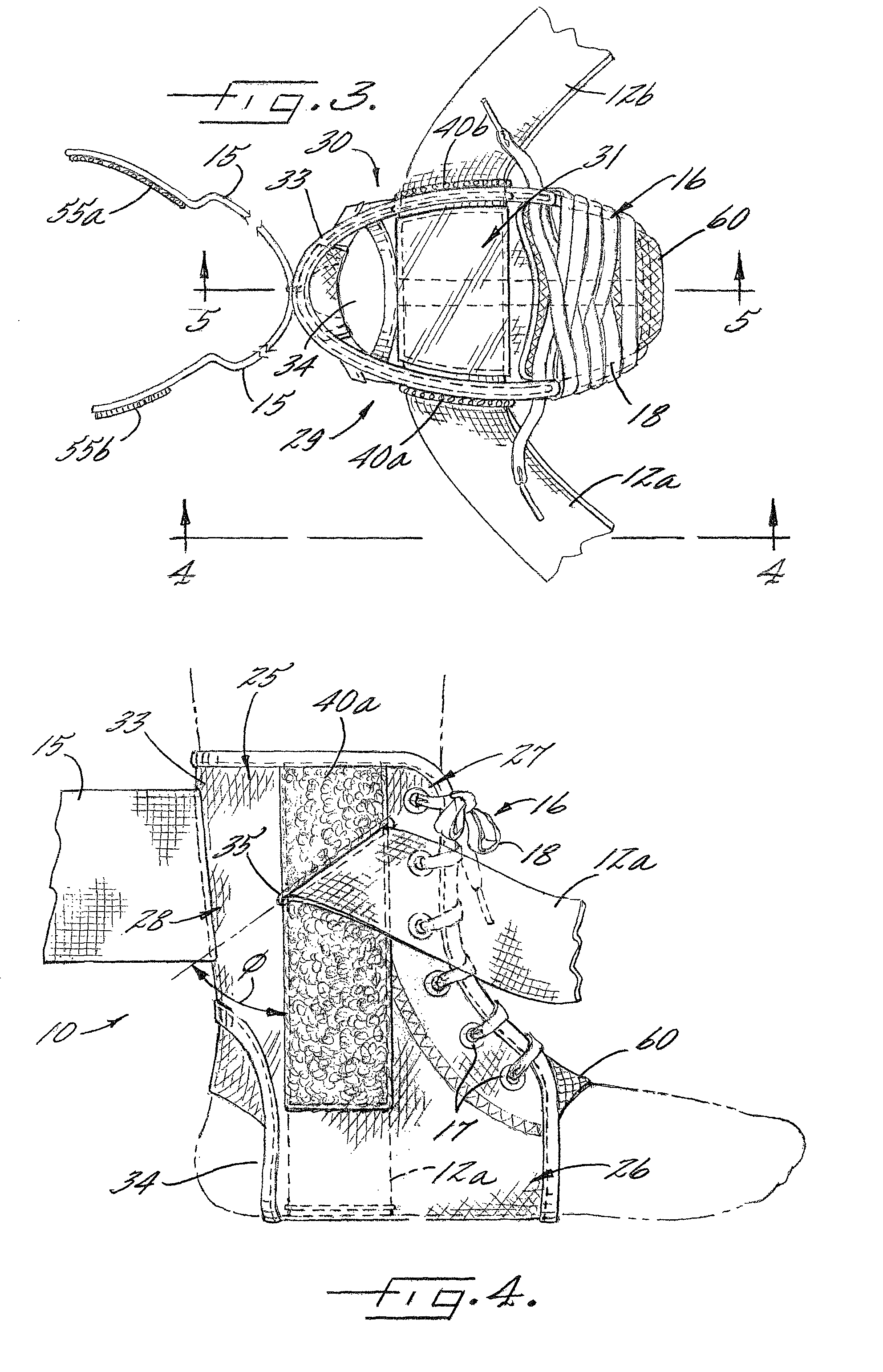
[0027]An overall view of an embodiment of an ankle apparatus of the invention is set forth at 10 in the perspective view of FIG. 1. The apparatus 10 may be worn without an athletic sock such that interior surfaces of the apparatus contact skin of the individual. Alternatively, the apparatus 10 may be worn over an athletic sock such that interior surfaces of the apparatus contact the sock. Further, the apparatus 10 is configured for wear on the right or lef...


PUM


Abstract

An ankle stabilizing apparatus for minimizing inversion and eversion of the foot, and more specifically, a body member having at least one cuff member positioned against a cuff portion of the body member, wherein the cuff member defines at least one opening for receiving at least one stabilizing strap such that the cuff and stabilizing strap dynamically apply a variable force against the body member and ankle. The apparatus promotes variable compression against the ankle upon application and during wear. The apparatus also resists distal migration during wear.

Description

CROSS-REFERENCE TO PRIORITY APPLICATIONS[0001]This application claims the benefit of commonly assigned PCT Application No. PCT / US08 / 52449, filed Jan. 30, 2008, in the U.S. Patent and Trademark Office, pending, which designates the U.S., and claims priority to commonly assigned U.S. Provisional Patent Application Ser. No. 60 / 982,543, filed Oct. 25, 2007, in the U.S. Patent and Trademark Office. This application incorporates the PCT and provisional applications by reference in their entirety.BACKGROUND OF THE INVENTION[0002]The invention relates to an ankle stabilizing apparatus for minimizing inversion and eversion of the foot, and more specifically, to a body member having at least one cuff member affixed to a cuff portion of the body member, wherein the cuff member defines at least one opening for receiving at least one stabilizing strap. As configured, the cuff and stabilizing strap dynamically apply a varying force against the body member and ankle during application and use. In ...

Claims


Application Information

Patent Timeline
Patent Type & Authority Patents(United States)
IPC IPC(8): A61F5/00A61F13/00
CPCA61F5/0111A61F5/0102
Inventor GAYLORD, ERIC, LEE
Owner MEDICAL SPECIALTIES
Why Eureka
Try Eureka