
Arrangement and method for the electromechanical drive for molding closing systems and calibration blow mandrel systems in blow molding machines

Active Publication Date: 2014-05-13
UNILOY MILACRON GERMANY
View PDF9 Cites 0 Cited by
  • Summary
  • Abstract
  • Description
  • Claims
  • Application Information

AI Technical Summary

Benefits of technology

The present invention relates to an electromechanical drive for mold closing systems and calibration blow mandrel systems in blow molding machines. The invention allows for fast movements and reliable maintenance of high closing and calibration forces with low effort and expense. The proposal includes a push mechanism, electric motor, and additional braking device that can hold the push rod in a specific position. This arrangement eliminates the need for additional elements to amplify forces and allows for easy adaptation to different mold thickness and calibration depth without requiring major modifications. The invention can be used with all mold closing systems and calibration systems that use directly acting hydraulic cylinders.

Problems solved by technology

Conventional electrical linear motors cannot maintain this build-up of force for a period of seconds or tens of seconds, as is required during a blow molding process.

Method used


Image

  • Arrangement and method for the electromechanical drive for molding closing systems and calibration blow mandrel systems in blow molding machines
  • Arrangement and method for the electromechanical drive for molding closing systems and calibration blow mandrel systems in blow molding machines

Examples


Embodiment Construction

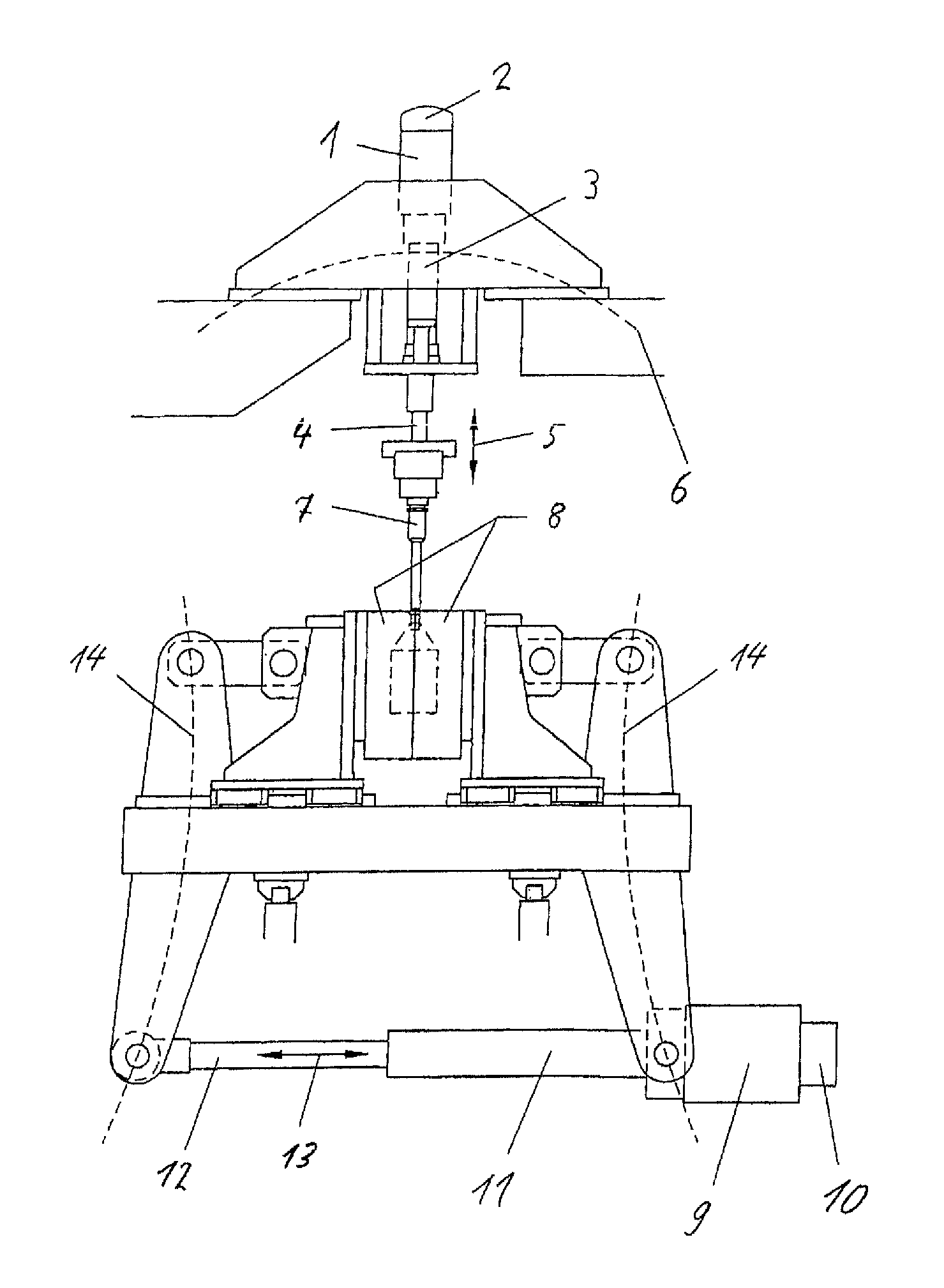
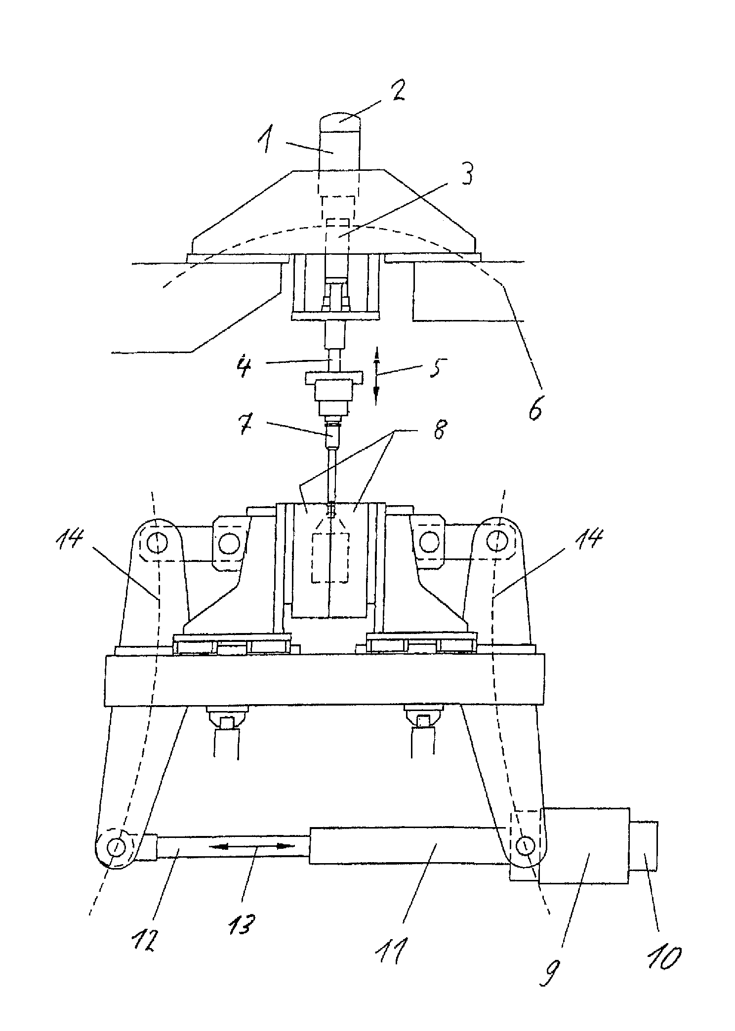
[0043]In FIG. 1, a cross-section through a mold closing system and a calibration blow mandrel system of a blow molding machine is shown.

[0044]The calibration blow mandrel system has exactly one electric motor 1, a braking device 2, a pushing mechanism 3, a push rod 4 and a calibration blow mandrel in calibrating position 7. The braking device 2 and the push mechanism 3 are arranged at the electric motor 1. The push rod 4 is arranged within the push mechanism 3 movable in movement directions 5. The calibration blow mandrel 7 is arranged at the push rod 4.

[0045]The mold closing system has exactly one electric motor 9, a braking device 10, a push mechanism 11, a push rod 12 and a blow mold 8, divided into two halves, into which the calibration blow mandrel 7 is introduced. The braking device 10 and the push mechanism 11 are arranged at the electric motor 9. The push rod 12 is arranged within the push mechanism 11 movable in movement directions 13. The mold halves 8 are each mounted on ...


PUM

PropertyMeasurementUnit
Fractionaaaaaaaaaa
Fractionaaaaaaaaaa
Timeaaaaaaaaaa

Abstract

The invention relates to an arrangement and to a method for the electromechanical drive for mold closing systems and calibration blow mandrel systems in blow molding machines, wherein the arrangement for the drive of an extrusion blow molding machine includes a push mechanism (3; 11), a push rod (4; 12) and exactly one electric motor (1; 9), wherein the push rod (4; 12) is movable by the push mechanism (3; 11) which is driven by the electric motor (1; 9), wherein the electric motor (1; 9) has an additional braking device (2; 10) which can be activated on the reaching of a required torque or a required force of the electric motor (2; 10) to hold the push rod (4; 12) in a state of maximum tension in its instantaneous position.

Description

FIELD OF INVENTION[0001]The invention relates to an arrangement and to a method for the electromechanical drive for mold closing systems and calibration blow mandrel systems in blow molding machines.BACKGROUND INFORMATION[0002]Drives for mold closing systems and calibration blow mandrel systems in blow molding machines on one hand need to be capable of performing fast movements in order to facilitate a rapid opening of the mold in connection with a swift removal of the molded article. On the other, they have to be able to apply, for a period of up to tens of seconds, the high forces required during the blow molding process. Currently, either hydraulic cylinders or several electric motors are employed for this purpose.[0003]Hydraulic cylinders, abeit meeting the aforementioned requirements, are highly energy-intensive, require regular and laborious maintenance, are not suited for cleanroom production and feature a low level of positioning accuracy.[0004]Even though electric motors do...

Claims


Application Information

Patent Timeline
IPC IPC(8): B29C49/76B29C49/56
CPCB29C49/56B29C49/04B29C49/4236B29C49/76B29C49/42362B29C49/5607B29C49/561B29C2049/5636
Inventor ARNDT, TORSTENNIMPSCH, NORBERTSZCZEPANSKI, STEFAN
Owner UNILOY MILACRON GERMANY
Learn More