Hybrid vehicle

a hybrid vehicle and hybrid technology, applied in the direction of engine-driven generator propulsion, electric devices, process and machine control, etc., can solve the problems of recovery loss of regenerative charging recovery, and possible area for regenerative charging recovery, so as to improve fuel consumption and reduce the possibility of regenerative charging loss

Inactive Publication Date: 2014-05-13
DENSO CORP +1
View PDF14 Cites 0 Cited by
  • Summary
  • Abstract
  • Description
  • Claims
  • Application Information

AI Technical Summary

Benefits of technology

[0011]In view of the above-described problem, it is an object of the present disclosure to provide a hybrid vehicle that can restrict a recovery loss of a regenerative charging.
[0013]The hybrid vehicle can restrict a recovery loss of a regenerative charging with restricting an increase in the temperature of the battery.
[0015]The hybrid vehicle restricts a situation that the temperature of the battery exceeds the predetermined temperature. Thus, a situation that the battery cannot be charged after the temperature of the battery exceeds the predetermined temperature can be restricted, and a recovery loss of the regenerative charging in the regenerative charging possible area can be restricted. As a result, fuel consumption can be improved.

Problems solved by technology

As a result, a recovery loss of a regenerative charging occurs.
However, in a case where the battery charge amount is reduced before is (sec) of the downhill running in prospect of the recovery loss Sm of the regenerative charging (a conventional art 2 in FIG. 6), the regenerative charging is performed throughout the downhill running.
In a case where there is an uphill in front of a downhill as shown in FIG. 7, if the EV running is performed on the uphill for reducing the battery charge amount, a feeling of strangeness in running may be caused.
However, the present inventors found that even when the hybrid vehicle switches to the EV running before the downhill, a recovery loss of the regenerative charging may occur.
As a result, charging is not performed even during the downhill running that is a running condition in which a regenerative charging is possible, and a recovery loss of the regenerative charging occurs.

Method used


Image

  • Hybrid vehicle
  • Hybrid vehicle
  • Hybrid vehicle

Examples


Embodiment Construction

[0024]Embodiments for achieving the present invention will be described with reference to the accompanying drawings.

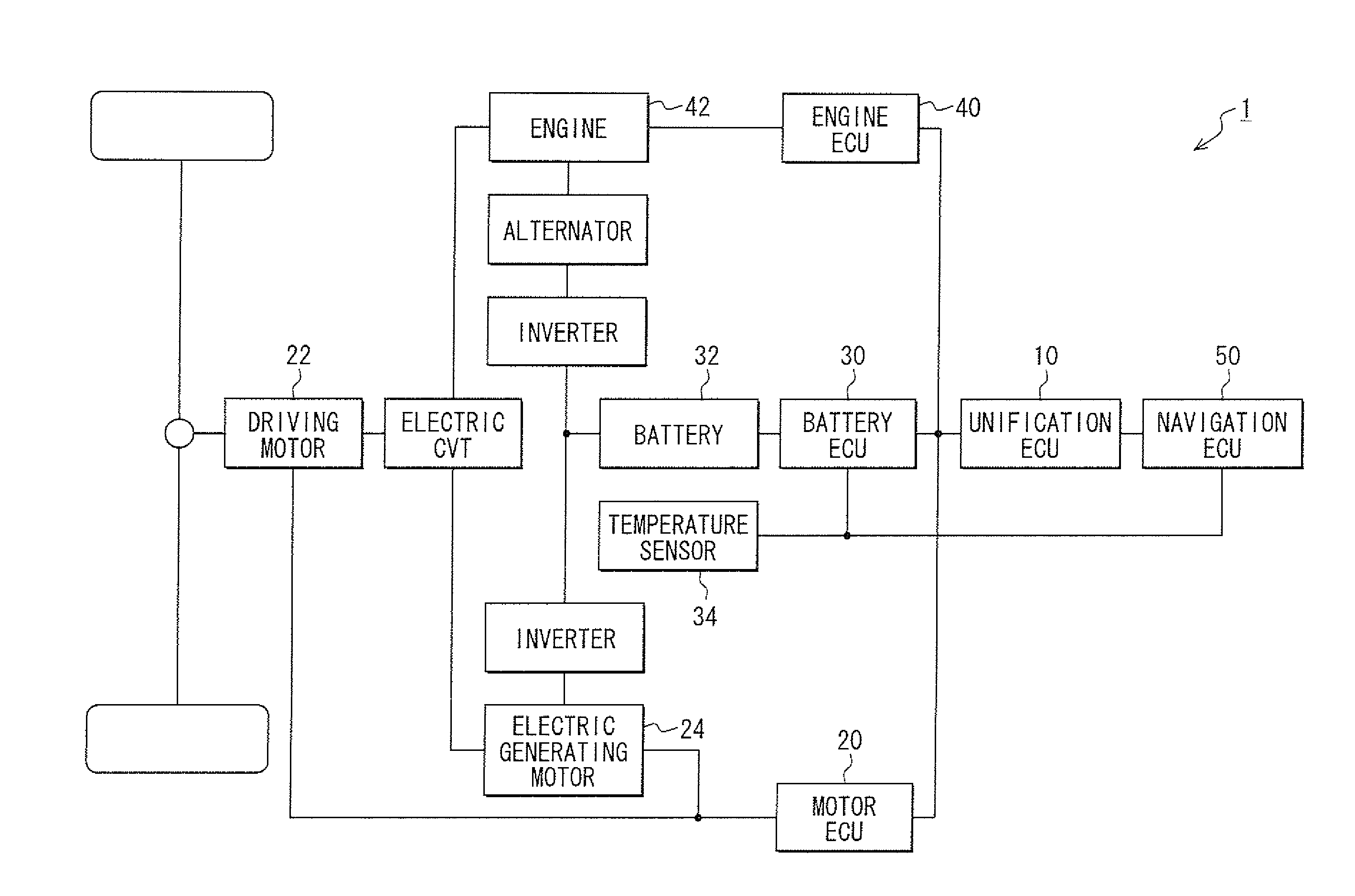
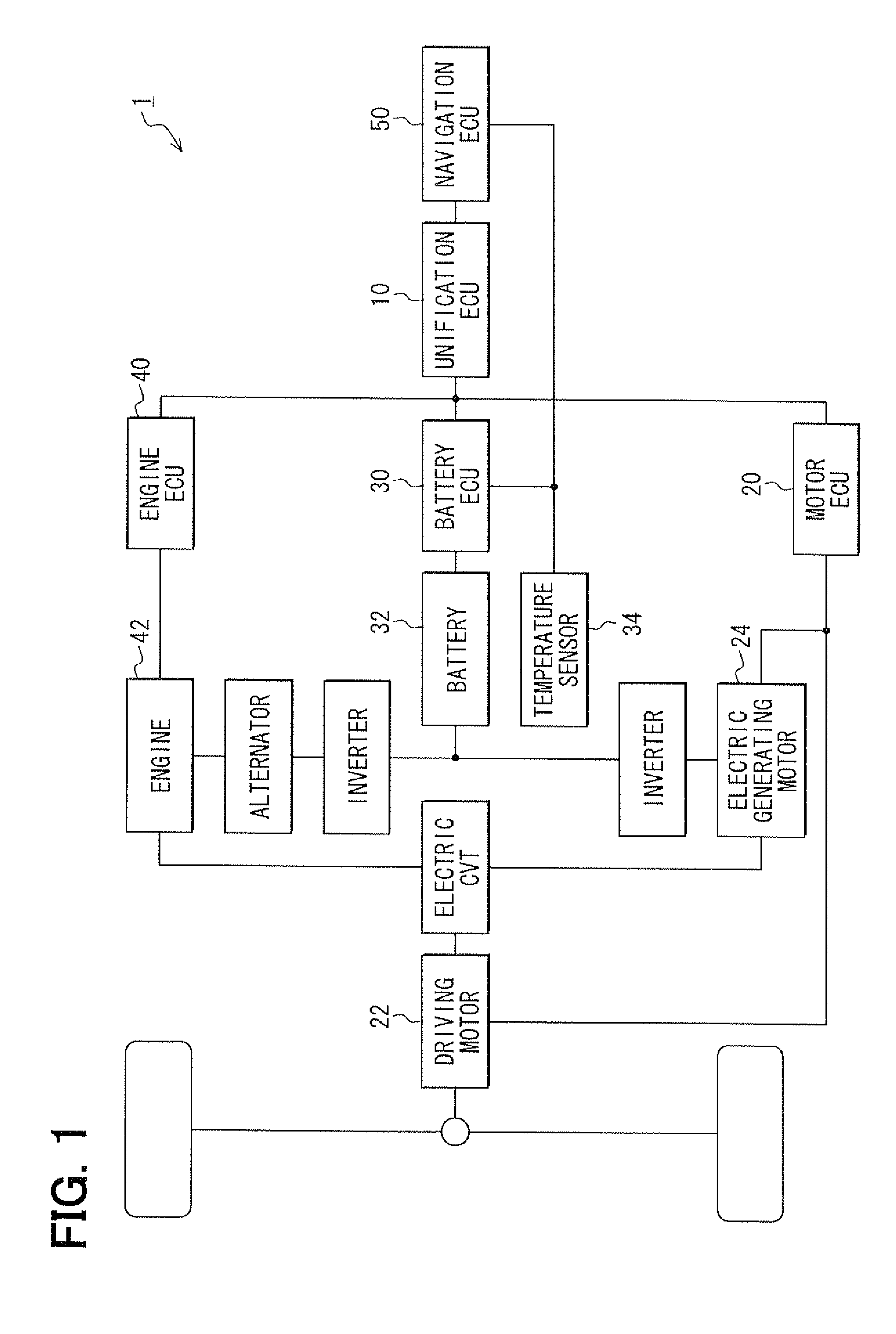
[0025]In FIG. 1, a system configuration diagram showing a hybrid vehicle according to an embodiment of the present invention is shown. A hybrid vehicle 1 is configured so that use ratios of a motor and an engine are settable and EV running and HEV running are switchable. Therefore, the hybrid vehicle 1 includes a plurality of components.

[0026]A unification ECU (electronic control unit) 10 is a section coupled with each of a motor ECU 20, a battery ECU 30, an engine ECU 40, and a navigation ECU 50 so as to be communicatable and unifying functions of these ECUs.

[0027]The motor ECU 20 is a section coupled with a driving motor 22 and an electric generating motor 24 and controlling them. The motor ECU 20 controls, for example, timings of starting / stopping and outputs of the motors 22, 24.

[0028]The battery ECU 30 is a section coupled with a battery 32 and a temperature senso...


PUM


Abstract

A hybrid vehicle includes a regenerative charging area detection section, a recovery loss estimation section, and a motor use ratio increase section. The regenerative charging area detection section detects arrival of a regenerative charging possible area in which a regenerative charging from a motor to a battery is possible. The recovery loss estimation section estimates a recovery loss of the regenerative charging based on a regenerative charge amount in the regenerative charging possible area and a current remaining battery amount in response to detection by the regenerative charging area detection section. In response to estimation by the recovery loss estimation section, before the arrival at the regenerative charging possible area, the motor use ratio increase section increases a use ratio of the motor so as to decrease a remaining battery amount while limiting the temperature of the battery to a predetermined temperature range.

Description

CROSS REFERENCE TO RELATED APPLICATIONS[0001]This application is a U.S. national stage of PCT / JP2010 / 002353 filed on Mar. 31, 2010, and is based on Japanese Patent Application No. 2009-85631 filed on Mar. 31, 2009, the disclosure of which is incorporated herein by reference.TECHNICAL FIELD[0002]The present invention relates to a hybrid vehicle.BACKGROUND[0003]Conventionally, hybrid vehicles that are switchable between running using a motor for driving (so called EV running) and running using the motor and an engine for driving (so called HEV running) are known. In the above-described hybrid vehicle, a technique for previously planning a switching between the EV running and the HEV running based on a route information and gradient information of a navigation system is known.[0004]The switching control of the EV running and the HEV running is disclosed, for example, in the following patent document 1. The patent document discloses a hybrid vehicle that is switchable between the EV run...

Claims


Application Information

Patent Timeline
Patent Type & Authority Patents(United States)
IPC IPC(8): B60K6/48B60W20/00B60L3/00B60W10/08B60W10/26B60W10/18B60W10/06
CPCB60W50/0097B60W2550/143B60W2710/244B60L3/0046Y02T10/6217B60K6/543B60W20/102B60L7/14B60L11/123B60W2710/246Y02T10/84B60L11/14B60L2240/545B60W2510/246Y02T10/7077Y02T10/6221B60L2240/36B60W30/18127Y02T10/7005B60K6/48B60W2510/244B60W20/11B60L50/16B60L50/61B60L58/12B60L58/24B60W2552/20Y02T10/62Y02T10/70Y02T10/7072
Inventor YAMADA, KAZUNAONAITO, TAKASHINIWA, TOSHIAKITAKAHARA, MASATOSHIOGAWA, FUMIHARUSUGANUMA, HIDEAKIKURAISHI, MAMORU
Owner DENSO CORP
Why Eureka
Try Eureka