
Method and system for routing optimally between terminals through intermediate vias in a circuit design

a circuit design and intermediate via technology, applied in the field of routing terminals through intermediate vias in a circuit design, can solve the problems of inability to accept input from a designer, inability to take into account design preferences or instructions, and difficulty in automating routing approaches

Active Publication Date: 2014-05-13
CADENCE DESIGN SYST INC
View PDF27 Cites 2 Cited by
  • Summary
  • Abstract
  • Description
  • Claims
  • Application Information

AI Technical Summary

Benefits of technology

[0009]It is a further object of the present invention to provide a system and method to automatically provide for groupings of vias into flow vias, allowing for the common manipulation of all vias in the flow via set.
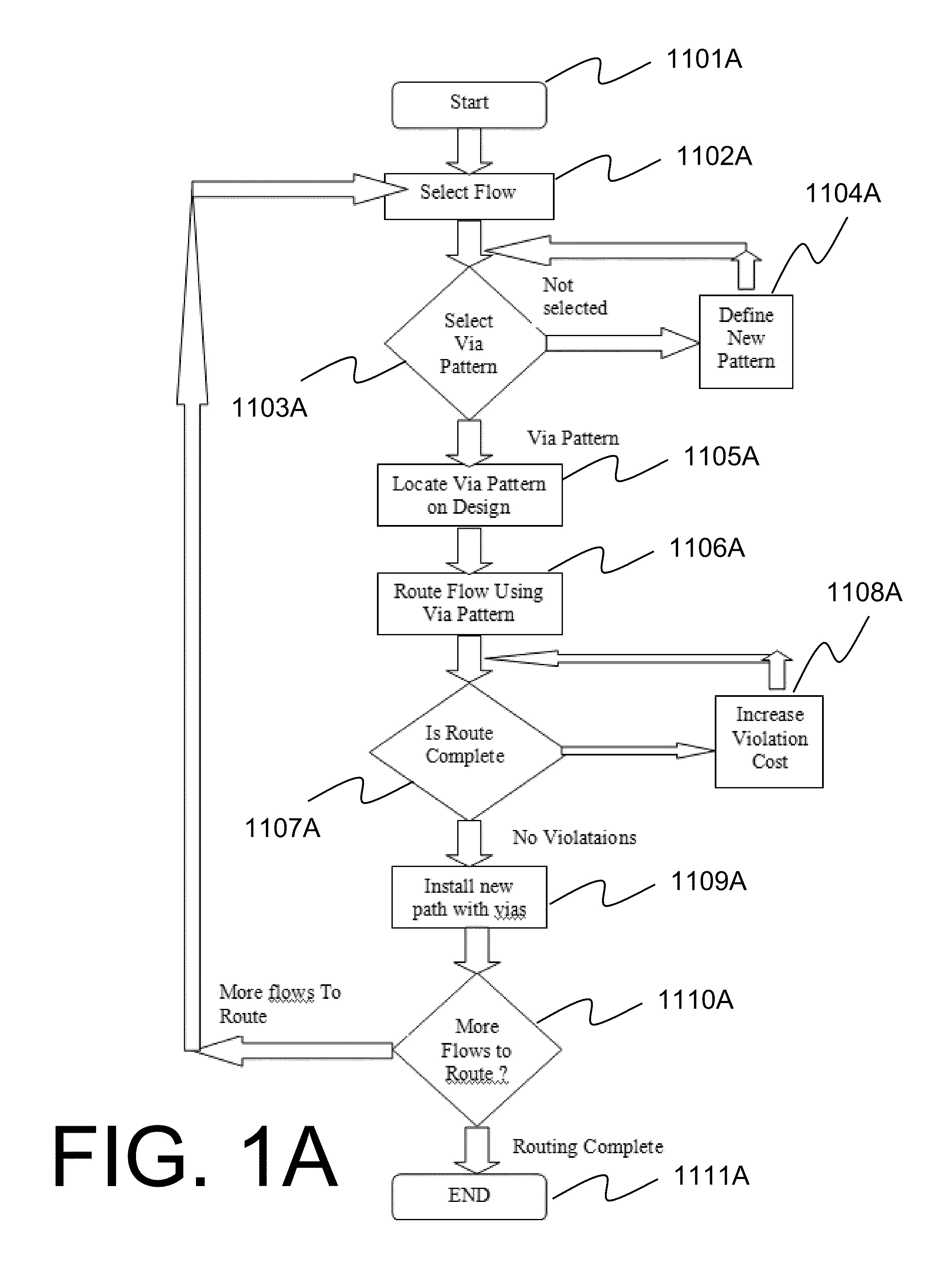
[0010]It is still a further object of the present invention to provide a system and method to allow the user to specifically locate the vias within a flow via or to use a predetermined flow via pattern which may include the intermixing of ground and power vias therein to provide, for example, shielding, more precise control of delay coordination, crosstalk / cross-coupling amelioration, phase control, and the like.
[0012]It is yet another object of the present invention to provide a system and method that is capable of routing bundles and flows of connections as one group to a flow via.
[0013]It is still a further object of the present invention to provide a system and method to provide clean routing responsive to user specifications.

Problems solved by technology

In generating the layout or silicon realization by a designer, a dichotomy exists separating the ability to manually specify certain paths or interconnections between components and a largely automated router type system where input from a designer is generally not able to be accepted.
Thus, on one hand, the manual layout of paths between components is a very arduous, time-consuming, and error-prone activity requiring many man hours from groups of engineers and often delaying product launch substantially but yet yielding a solution that meets certain requirements.
On the other hand, an automated routing approach generally lacks the ability to take as input certain design preferences or instructions from the designers.
Thus, the conventional automated routing approach, while it may be quicker, may not arrive at the optimum or desired solutions.
Moreover, auto routers in the past have generally not been suitably configurable.
Unfortunately, this results in a haphazard scattering of vias throughout the circuitboard or integrated circuit (used interchangeably herein) and is often sub-optimal.
Often each independent connection is calculated to be the most efficient and thereby, the connection between components will suffer from different lengths resulting in delay issues between the signals.
Indeed, differential pairs may pose problems that require manual intervention to resolve, as will phase, cross coupling, and the like.
The end result of such auto-routers generally is a lack of clean routing paths with a largely random or non-matching pattern.
Still further, auto-routers of the past have not allowed for the intermixing of ground and power vias as needed.
The user has heretofore been unable to even specify the location of each via to meet design needs.

Method used


Image

  • Method and system for routing optimally between terminals through intermediate vias in a circuit design
  • Method and system for routing optimally between terminals through intermediate vias in a circuit design
  • Method and system for routing optimally between terminals through intermediate vias in a circuit design

Examples


Embodiment Construction

[0064]Reference will now be made in detail to the embodiments of the present general inventive concept, examples of which are illustrated in the accompanying Drawings, wherein like reference numerals refer to like elements throughout. It is to be understood that while disclosed with reference to exemplary embodiments described below, the present invention is not limited to such illustrative embodiments themselves.

[0065]Systems, connected components, integrated circuits (ICs), microchips, systems-on-chip, circuitboards, and the like, may be modeled in a variety of different ways in an electronic design automation (EDA) flow. For example, some of the ways of modeling a system include a merely logical schematic diagram which omits all physical characteristics or dimensionality and merely shows simplified or abstracted representations of components or cells within the device.

[0066]Another manner of representing a system is a physical layout which shows an almost fully elaborated schemat...


PUM


Abstract

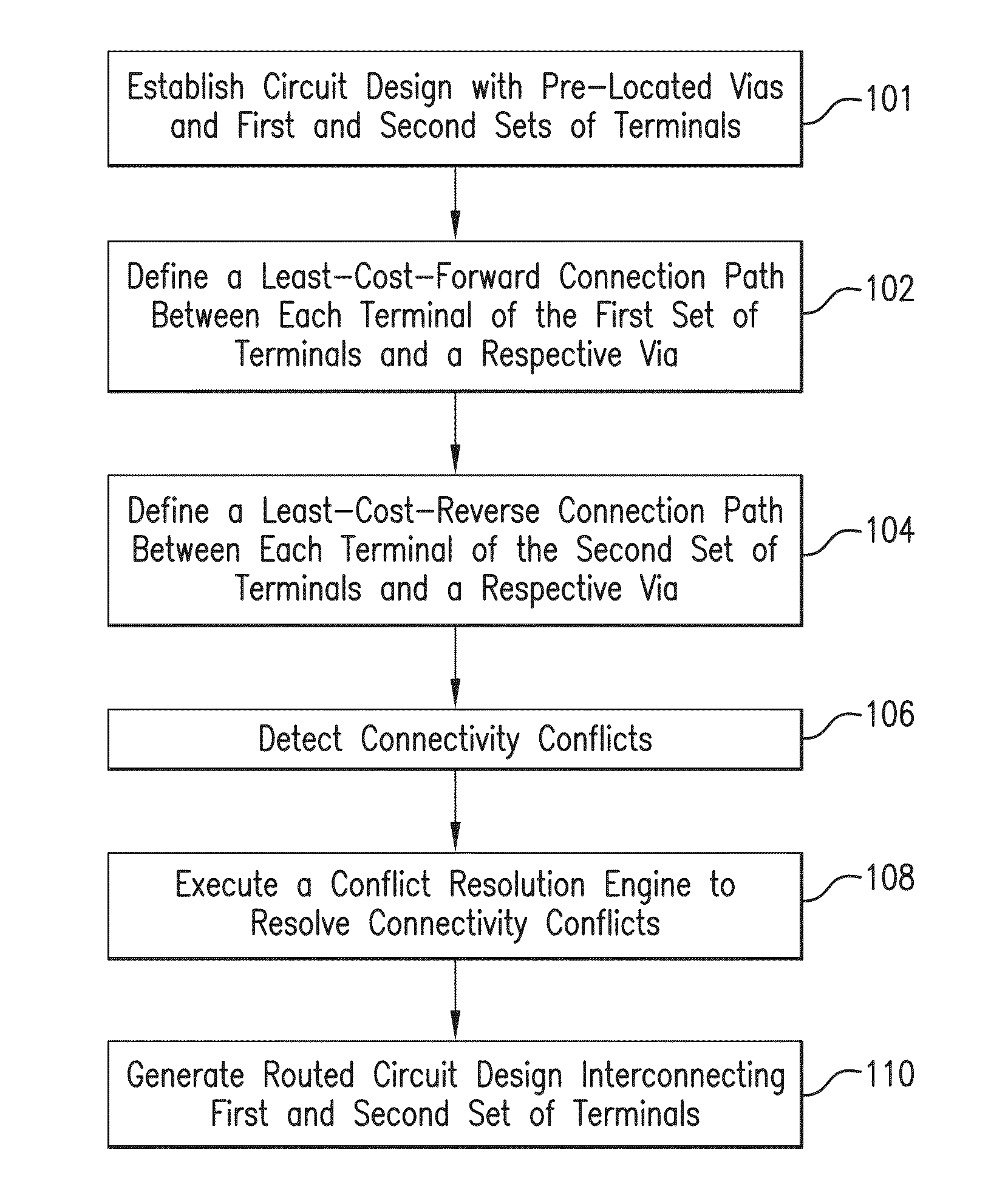
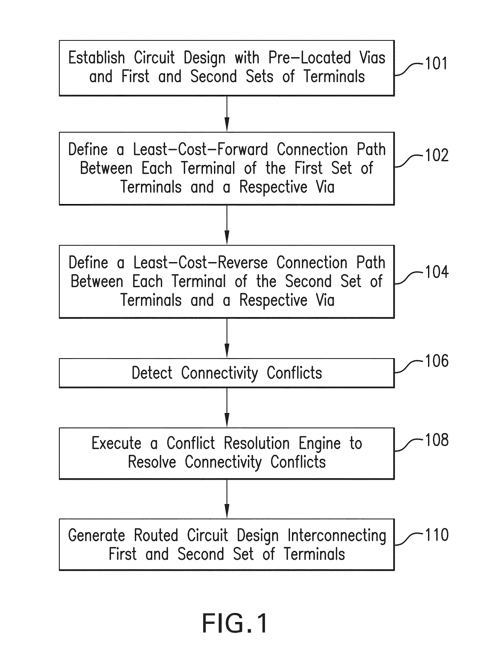
A system and method are provided for establishing an automated routing environment in an electronic design automation (EDA) work flow for the routing of a circuit design. A user may merely specify a flow via pattern, a flow via location, and a start and end terminal and thereby, the auto router or path finder will automatically find the least-cost paths between each of the start terminals through at least one intermediate via of the flow via and ending at an end terminal. Upon successful routing of all needed terminals, an at least partially routed circuit design may be output.

Description

RELATED APPLICATIONS[0001]This application is a Divisional patent application of application Ser. No. 13 / 432,904, filed on 28 Mar. 2012, now U.S. Pat. No. 8,464,196. The entire disclosure of the prior application Ser. No. 13 / 432,904, from which an oath or declaration is supplied, is considered a part of the disclosure of the accompanying Divisional application and is hereby incorporated by reference.BACKGROUND OF THE INVENTION[0002]The subject system and method are generally directed to routing terminals through intermediate vias in a circuit design. The system and method provide automated measures for interacting with a developer, providing a developer with an autorouter capable of pathfinding, cost optimizing, and routing selectively to and from intermediate vias disposed between terminals. The system and method also provide flow vias which maintain a relationship between a plurality of vias collectively and are thereby manipulable as a group. As electronic design automation (EDA)...

Claims


Application Information

Patent Timeline
Patent Type & Authority Patents(United States)
IPC IPC(8): G06F17/50
CPCG06F17/5077G06F30/394
Inventor LAWSON, RANDALL SCOTTBERGAN, SEANSMEDLEY, JOSEPH DEXTERMUSTO, PAUL S.NEAL, BRETT ALLENWOODWARD, JR., RICHARD ALLENRADUMILO-FRANKLIN, JELENAFARMAR, FRANKHORLICK, GREGORY M.
Owner CADENCE DESIGN SYST INC
Learn More