Supercharge Your Innovation With Domain-Expert AI Agents!

Internal pedicle insulator apparatus and method of use

a technology of pedicles and insulators, applied in the field of surgical instruments and tools, can solve the problems of nerve root irritation, reduced motor skills or even paralysis, impedance or damage to spinal cord or nerve roots, etc., and achieve the effect of preventing nerve root irritation

Active Publication Date: 2014-05-20
CHAP MED INC
View PDF10 Cites 3 Cited by
  • Summary
  • Abstract
  • Description
  • Claims
  • Application Information

AI Technical Summary

Benefits of technology

The apparatus effectively prevents nerve root irritation by positioning an insulator implant between nerves and stabilizing materials, reducing the risk of impingement and damage during spinal stabilization procedures.

Problems solved by technology

The degeneration of any portion of the lumbar spine can result in instability of the spine, which can lead to impingement or damage to the spinal cord or nerve roots.
Impingement of the spinal column or nerve root can result in pain.
Damage to spinal cord or nerve roots can result in reduced motor skills or even paralysis.
However, even after repositioning there may be an effect on the pedicle wall, which can still cause nerve root irritation.
Such procedures are also susceptible to loosening of the screw.
Thus, a heretofore unaddressed need exists in the industry to address the aforementioned deficiencies and inadequacies.

Method used


Image

  • Internal pedicle insulator apparatus and method of use
  • Internal pedicle insulator apparatus and method of use
  • Internal pedicle insulator apparatus and method of use

Examples


Embodiment Construction

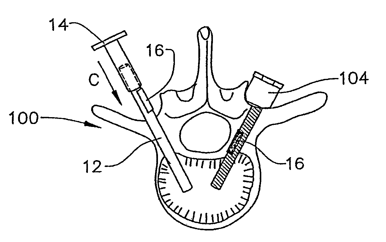
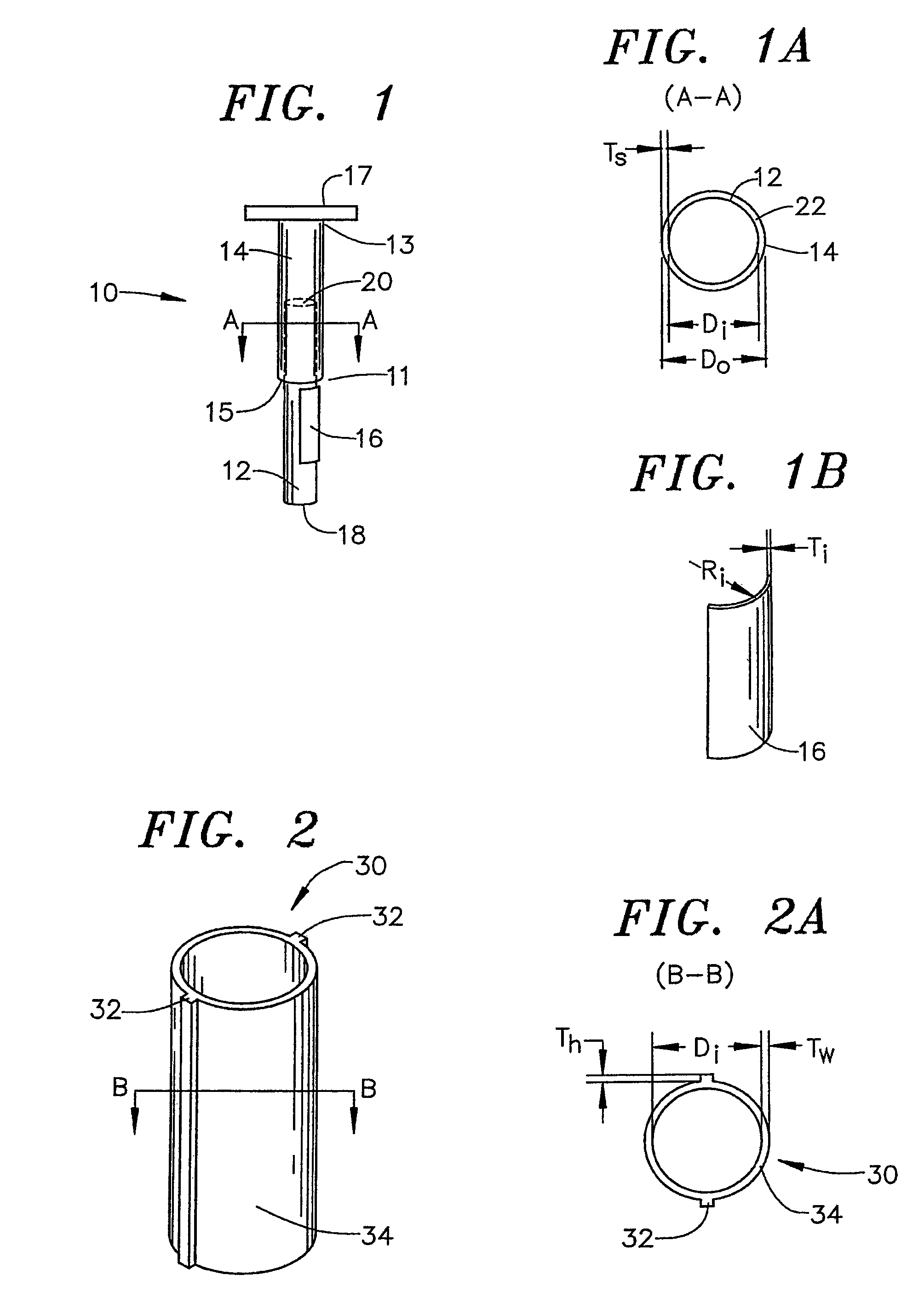
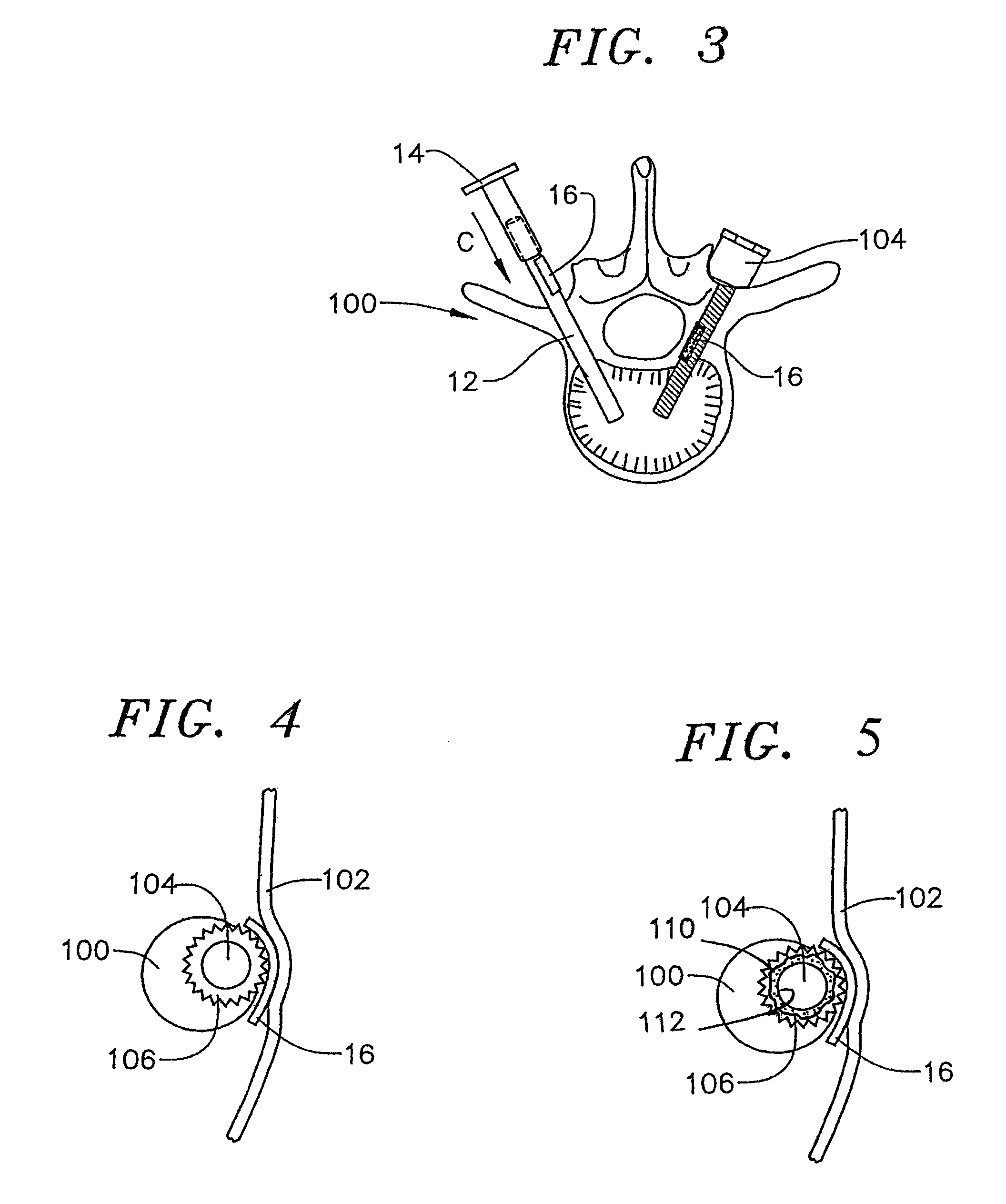
[0021]FIG. 1 illustrates one preferred embodiment of an internal pedicle insulator apparatus 10. The internal pedicle insulator apparatus 10 comprises an inner insertion rod 12, an outer insertion rod 14, and an internal pedicle insulator implant 16.

[0022]The inner insertion rod 12 has a bottom end 18 and an opposing top end 20. It is preferable that the inner insertion rod 12 has a substantially round cross-section. However, it should be noted that the inner insertion rod 12 can comprise any suitable configuration. The inner insertion rod 12 can comprise any suitable material, such as titanium, as merely one example.

[0023]The outer insertion rod 14 has a lower end 11 and an opposing upper end 13. An opening 15 is disposed at the lower end 11. An optional handle 17 can be disposed toward the upper end 13 of the outer insertion rod 14 to facilitate use of the internal pedicle insulator apparatus 10. An opening at the upper end 13 of the outer insertion rod 14 through which the inner ...


PUM


Abstract

Internal pedicle insulator apparatuses and methods are provided. A representative method includes: providing an internal pedicle insulator implant; inserting the implant into a pedicle such that the implant is positioned between a nerve and material that is to be applied in a vicinity of the nerve; applying the material in the vicinity of the nerve; and using the implant to prevent the material from contacting the nerve.

Description

CROSS-REFERENCE TO RELATED APPLICATIONS[0001]This application is a Continuation-in-Part application, which claims priority to U.S. patent application entitled, “Internal Pedicle Insulator Apparatus and Method of Use,” having Ser. No. 11 / 110,005 filed on Apr. 20, 2005, now U.S. Pat. No. 7,338,500, which claims priority to U.S. provisional application entitled, “Internal Pedicle Insulator Apparatus” having Ser. No. 60 / 563,797 filed on Apr. 20, 2004, both of which are entirely incorporated herein by reference.FIELD OF THE INVENTION[0002]The present invention generally relates to surgical instruments and tools, and in particular, relates to an internal pedicle insulator apparatus.BACKGROUND OF THE INVENTION[0003]The human spine is composed of a column of thirty-three bones, called vertebra, and their adjoining structures. The twenty-four vertebrae nearest the head are separate bones capable of individual movement and are generally connected by anterior and posterior longitudinal ligamen...

Claims


Application Information

Patent Timeline
Patent Type & Authority Patents(United States)
IPC IPC(8): A61B17/68A61B17/84A61B17/58A61B17/70A61B17/88
CPCA61B17/7098A61F2002/4631A61B17/70A61B17/686A61B17/7001
Inventor CHAPPUIS, JAMES, L.
Owner CHAP MED INC
Features
  • R&D
  • Intellectual Property
  • Life Sciences
  • Materials
  • Tech Scout
  • Unparalleled Data Quality
  • Higher Quality Content
  • 60% Fewer Hallucinations
Learn More