Method for manufacturing semiconductor device
a semiconductor and manufacturing method technology, applied in semiconductor devices, semiconductor/solid-state device details, electrical apparatus, etc., can solve the problems of chip dent, gap between the design value change in the distance between the circuit pattern and the lid, so as to reduce the dicing speed and the actual value, the blade cost is increased, and the accuracy of dicing is lowered.
- Summary
- Abstract
- Description
- Claims
- Application Information
AI Technical Summary
Benefits of technology
Problems solved by technology
Method used
Image
Examples
first embodiment
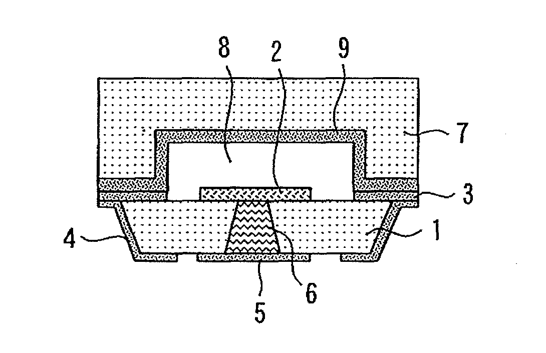
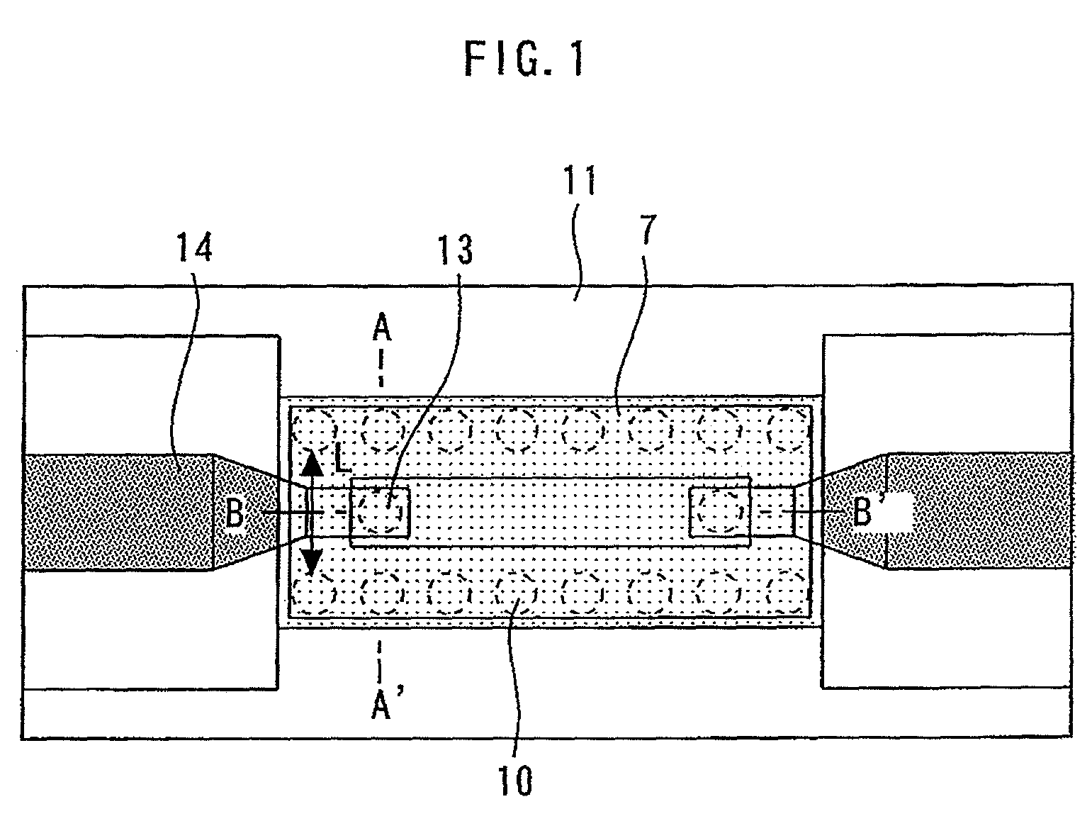
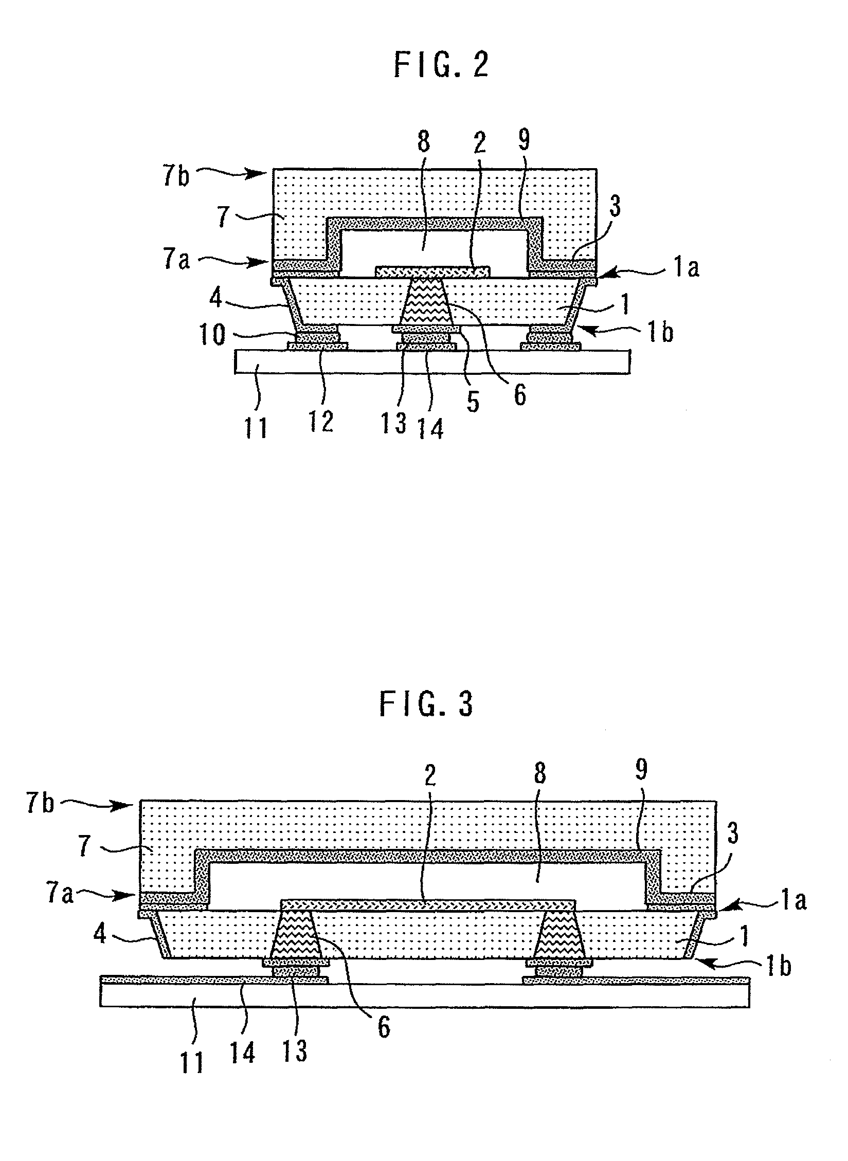
[0032]FIG. 1 is a plan view showing a semiconductor device according to the first embodiment. FIG. 2 is a sectional view taken along the line A-A′ in FIG. 1. FIG. 3 is a sectional view taken along the line B-B′ in FIG. 1.
[0033]A body wafer 1 has a major surface 1a and a major surface 1b facing to each other. A circuit pattern 2 and a metal film 3 are formed on the major surface 1a of the body wafer 1.
[0034]A metal film 4 is formed on the side surface of the body wafer 1 and a part of the major surface 1b, and the metal film 4 is connected to the metal film 3. A pad 5 for inputting / outputting signals is formed on the major surface 1b of the body wafer 1. The pad 5 for inputting / outputting signals is connected to the circuit pattern 2 by penetrating electrodes 6 penetrating through the body wafer 1.
[0035]The circuit pattern 2 is a circuit pattern for an amplifier and an oscillator, and has transistors, resistors, MIM capacitors, spiral inductors, wirings and the like. The through-hole...
second embodiment
[0052]A method for manufacturing a semiconductor device according to the second embodiment will be described. FIGS. 13 to 18 are sectional views for illustrating the method for manufacturing a semiconductor device according to the second embodiment.
[0053]First, in the same manner as in the first embodiment, steps shown in FIGS. 4 to 7 are performed. Next, as shown in FIG. 13, a metal film 19 and a recess 8 are formed on the major surface 7a of the lid wafer 7. Next, as shown in FIG. 14, a through-hole 20 penetrating the lid wafer 7 from the major surface 7b of the lid wafer 7 and reaching the metal film 19 is formed.
[0054]Next, as shown in FIG. 15, a metal film 21 is formed on the major surface 7b of the lid wafer 7, the inner wall of the through-hole 20, and the metal film 19 exposed in the through-hole 20.
[0055]Next, as shown in FIG. 16, a recess 8 is made to face to the circuit pattern 2, the through-hole 17 is aligned with the through-hole 20, and the metal film 3 is made to con...
third embodiment
[0059]A method for manufacturing a semiconductor device according to the third embodiment will be described. FIGS. 19 to 26 are sectional views for illustrating the method for manufacturing a semiconductor device according to the third embodiment.
[0060]First, as shown in FIG. 19, a circuit pattern 2 is formed on the major surface 1a of the body wafer 1.
[0061]Next, as shown in FIG. 20, a resist pattern 18 is formed on the major surface 7a of the lid wafer 7. The lid wafer 7 is subjected to etching using the resist pattern 18 as a mask. Thereby, a recess 8 is formed on the major surface 7a of the lid wafer 7.
[0062]Next, as shown in FIG. 21, the recess 8 is made to face to the circuit pattern 2, the semiconductors on the major surface 1a of the body wafer 1 are made to contact the semiconductors on the major surface 7a of the lid wafer 7, and the lid wafer 7 is joined to the body wafer 1 using plasma activation joining or the like.
[0063]Next, as shown in FIG. 22, the body wafer 1 and t...
PUM
| Property | Measurement | Unit |
|---|---|---|
| wavelength | aaaaa | aaaaa |
| frequency | aaaaa | aaaaa |
| wavelength | aaaaa | aaaaa |
Abstract
Description
Claims
Application Information
 - R&D
- Intellectual Property
- Life Sciences
- Materials
- Tech Scout
- Unparalleled Data Quality
- Higher Quality Content
- 60% Fewer Hallucinations
Browse by: Latest US Patents, China's latest patents, Technical Efficacy Thesaurus, Application Domain, Technology Topic, Popular Technical Reports.
© 2025 PatSnap. All rights reserved.Legal|Privacy policy|Modern Slavery Act Transparency Statement|Sitemap|About US| Contact US: help@patsnap.com


