Method and apparatus for performing continuous tubing operations

a technology of continuous tubing and tubing cylinders, which is applied in the direction of drilling casings, drilling pipes, borehole/well accessories, etc., can solve the problems of difficult, if not impossible, setting of conventional production platforms, and significant oil and gas exploration and production operations have shifted to more challenging environments, and conventional coiled tubing units in general, and injector heads in particular, are typically not well suited or cost effective for such uses

Inactive Publication Date: 2014-05-27
COLES ROBERT A
View PDF25 Cites 15 Cited by
  • Summary
  • Abstract
  • Description
  • Claims
  • Application Information

AI Technical Summary

Benefits of technology

[0014]The present invention comprises an apparatus capable of deploying multiple lengths of continuous tubing in a well, pipeline or other similar environment. The tubing can be deployed in many different manners including, but not necessarily limited to, over the side of a vessel or through the moon pool of a drilling rig or other vessel, without the need of a separate lifting or translating device such as an injector head. In the preferred embodiment, the present invention can permit the simultaneous deployment and retrieval of two separate continuous tubing strings. Moreover, the present invention further enables simultaneous pumping through either or both strings, as well as simultaneous flow back through either or both strings, including during periods when such continuous tubing strings are moving or stationary.
[0015]In the preferred embodiment, the present invention comprises a spool assembly having a central drum. Said spool assembly is rotatable about a central axis; in most cases, said axis has a substantially horizontal orientation. At least one string of continuous tubing is reeled or spooled around the drum of said spool assembly. Further, said drum can be rotated through the use of hydraulic motor and gear assemblies. Such motor and gear assemblies permit rotation of said drum in both forward and reverse, as well as a separate braking system independent of the drive system to ensure the drum remains stationary when desired. The spool assembly beneficially has sufficient pulling capacity to deploy as well as retrieve the entire length of spooled tubing, as well as a variety of fluids that the tubing may contain without the help of any outside force(s) such as auxiliary winches or buoyancy devices.
[0016]In the preferred embodiment, the spool assembly of the present invention has at least two independent braking systems. The first is a disc and caliper system, while a secondary braking system is integrated in the hydraulic motors used to rotate the spool assembly drum. The spool assembly also has a counterbalance valve system used to keep the drum stationary when no hydraulic pressure is applied, thereby serving as an additional safety feature.
[0021]Because the level-wind guide assembly is separate from the spool assembly, it affords great flexibility in placement of the spool assembly. If the level-wind and sheave were fixed to the spool assembly, a user would have to place the spool assembly near the entry point (i.e., the edge of the vessel or moon pool). With the present invention, only the level-wind assembly must be located in proximity to the entry point. Because the spool assembly is relatively heavy, this flexibility permits the spool assembly to be moved around a vessel as needed for ballasting purposes.
[0023]A hydraulic power unit driven by either an electric motor or diesel engine provides the power necessary to drive the main winch drum, brake system and level-wind guide sheave assemblies, as well as any other functions needed by the system. The control system is either mounted directly to the hydraulic power unit, is part of a remote operating panel, or a combination of the two. The control panel permits operation of every function of the system from a single point. The control panel also allows a user to connect and control additional spool and level-wind assemblies to the same panel, and control them independent of each other.

Problems solved by technology

As the world's supply of easily accessible oil and gas reserves becomes depleted, significant oil and gas exploration and production operations have shifted to more challenging environments, including deep-water locations.
Wells drilled on such locations are often situated in thousands of feet of water, which makes setting of conventional production platforms extremely difficult, if not impossible.
If the water depth is such that use of a standard hose assembly is not feasible, coiled tubing units are sometimes used.
However, conventional coiled tubing units in general, and injector heads in particular, are typically not well suited or cost effective for such uses.

Method used


Image

  • Method and apparatus for performing continuous tubing operations
  • Method and apparatus for performing continuous tubing operations
  • Method and apparatus for performing continuous tubing operations

Examples


Embodiment Construction

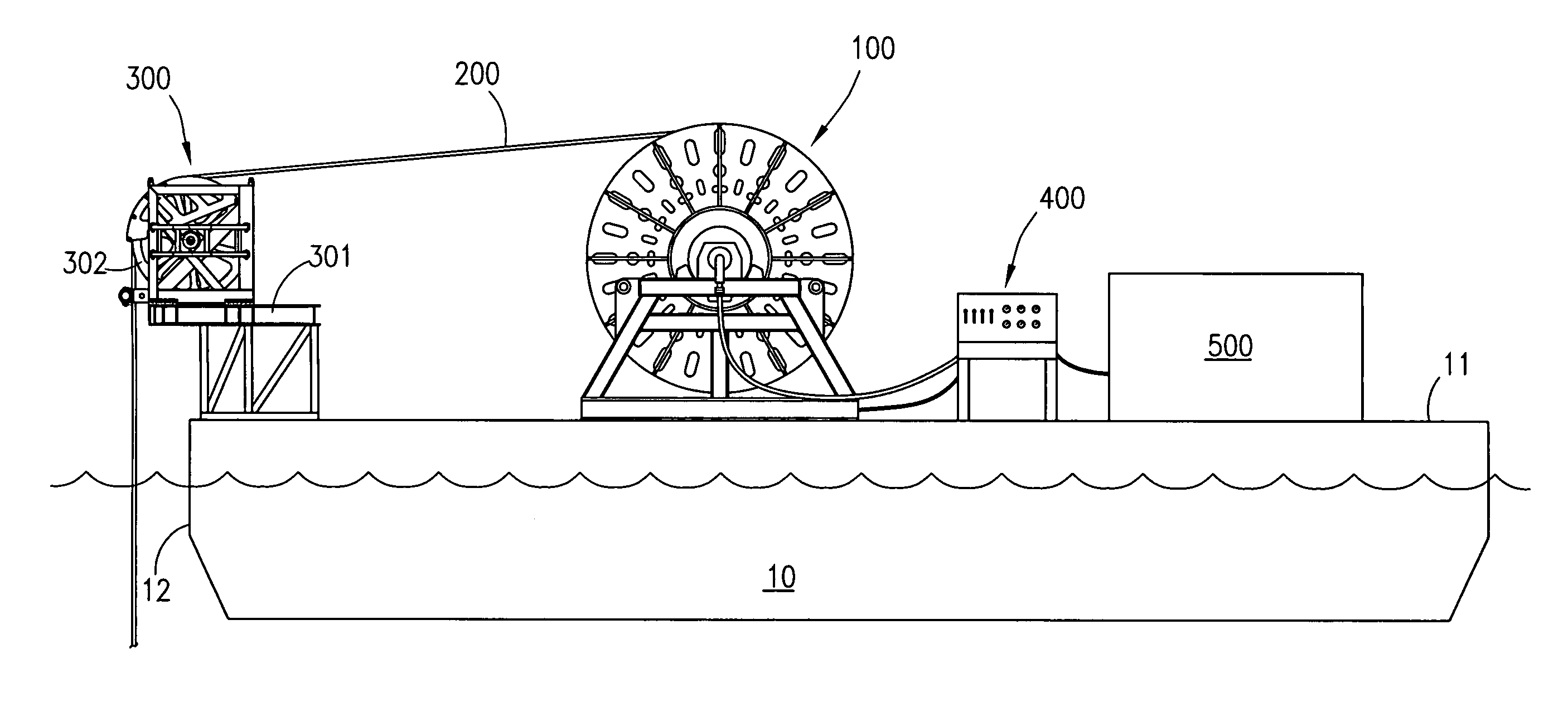
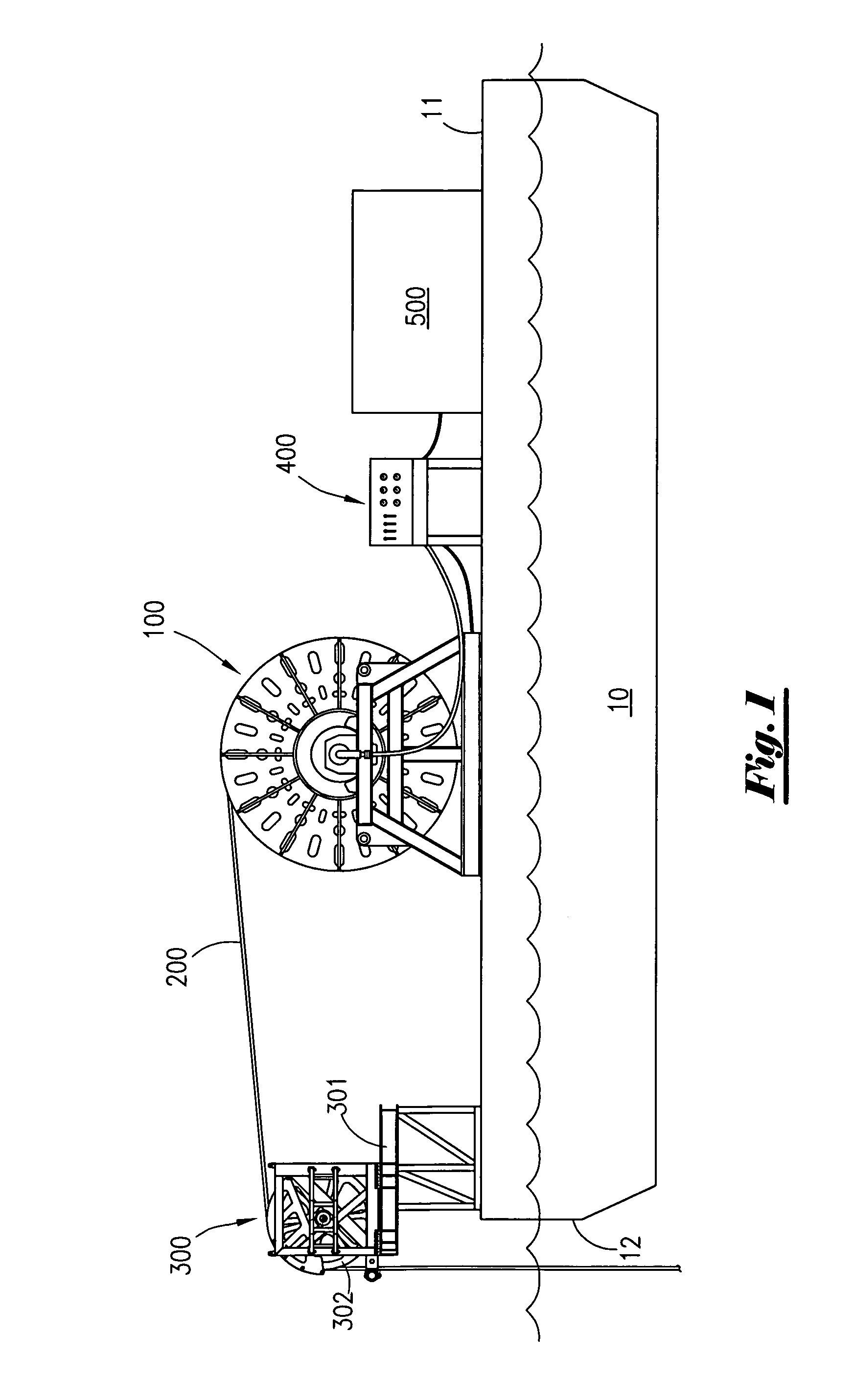
[0034]As set forth above, the present invention comprises an apparatus capable of deploying multiple lengths of continuous tubing in wells, pipelines or other similar environments without requiring use of a separate lifting or translating device such as a conventional injector head or other similar equipment.

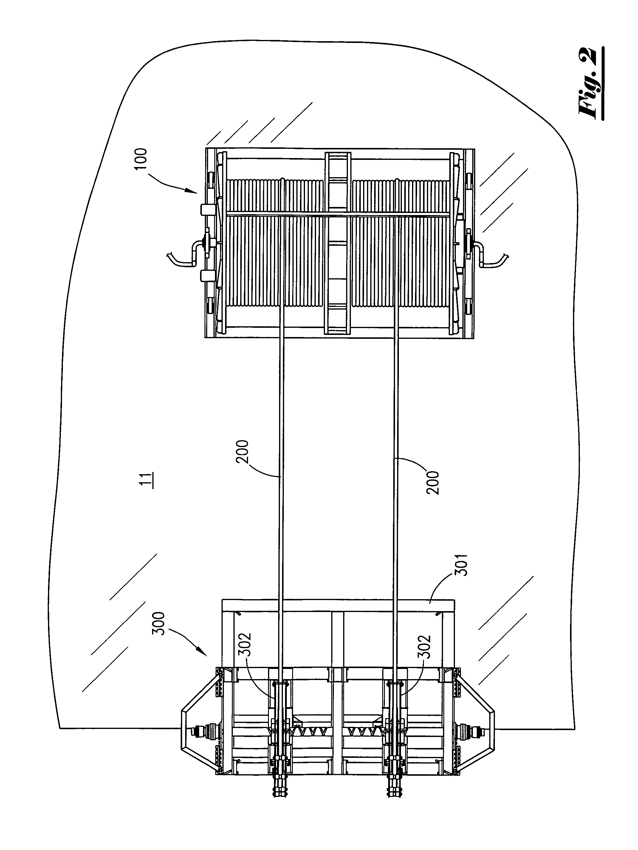
[0035]By way of illustration, but not limitation, the apparatus of the present invention permits simultaneous deployment of multiple strings of continuous tubing over the side of boats, through the moon pools of drilling rigs, and in connection with other vessels. In the preferred embodiment, the present invention can permit the simultaneous deployment and retrieval of multiple, separate strings of continuous tubing. Moreover, the present invention further enables simultaneous pumping through either or both strings, as well as simultaneous flow back through either or both strings, including during periods when the individual continuous tubing strings are moving or stationary. Fu...


PUM


Abstract

A spool for deploying and retrieving multiple separate strings of continuous tubing, such as over the side of or through the moon pool of a boat, rig or other vessel, without the need of an injector head. The spool has at least one rotating swivel to permit pumping of fluid(s) down, or back up, tubing strings while the spool is rotating or stationary. A level-wind assembly having at least one sheave directs the continuous tubing overboard, but also level-winds the tubing onto the spool in an orderly fashion through lateral movement of the sheave. The system is powered by a hydraulic power unit with a remote control console.

Description

CROSS REFERENCES TO RELATED APPLICATION[0001]Priority of U.S. Provisional Patent Application Ser. No. 61 / 268,750 filed Jun. 11, 2009 and Application Ser. No. 61 / 268,740 filed Jun. 16, 2009, both incorporated herein by reference, is hereby claimed.STATEMENTS AS TO THE RIGHTS TO THE INVENTION MADE UNDER FEDERALLY SPONSORED RESEARCH AND DEVELOPMENT[0002]NoneBACKGROUND OF THE INVENTION[0003]1. Field of the Invention[0004]The present invention pertains for a method and apparatus for performing continuous tubing operations. More particularly, the present invention relates to a system for performing continuous tubing operations in connection with subsea wells and pipelines. More particularly still, the present invention pertains to a continuous tubing system that can be used to pump fluid(s) into subsea wells or pipelines, or that can accommodate fluid flow from said subsea wells or pipelines.[0005]2. Brief Description of the Prior Art[0006]Continuous tubing systems—commonly referred to as...

Claims


Application Information

Patent Timeline
Patent Type & Authority Patents(United States)
IPC IPC(8): E21B19/22
CPCE21B19/22B65H75/425B65H75/4407B65H2701/33
Inventor COLES, ROBERT, A.
Owner COLES ROBERT A
Why Eureka
Try Eureka