Magnetic element

a technology of magnetic elements and lead wires, applied in the direction of transformers/reacts mounting/support/suspension, cores/yokes, transformers/inductances magnetic cores, etc., can solve the problems of wires being prone to breakage and thin wires being further liable to breakage, so as to reduce the contact position of the end, the effect of preventing the breakage of lead wires and increasing the number of windings

Active Publication Date: 2014-05-27
SUMIDA CORP
View PDF31 Cites 3 Cited by
  • Summary
  • Abstract
  • Description
  • Claims
  • Application Information

AI Technical Summary

Benefits of technology

[0010]In such a structure, by the cutout part provided in the second core member, an end of the lead wire forming the coil is guided to the binding terminal part via this cutout part. Then, the existence of this cutout part enables to create a state that the end of the lead wire does not contact the second core member. In this structure, it is possible to prevent a contact between the second core member and the end. Thus, when the magnetic element is used in an environment where vibrations are given, breakage of the lead wire at a contact portion of the second core member and the end can be prevented. Since breakage of the lead wire can be prevented effectively in an environment where vibrations are given, the number of windings of the coil can be increased using a thin wire having a smaller diameter as the lead wire, and it is possible to increase the inductance value of the magnetic element.
[0012]In such a structure, the end of the lead wire forming the coil is guided to the binding terminal part while the end is prevented from contacting the outer peripheral edge of the one flange part of the first core member. Accordingly, it is possible to further decrease the contact position of the end, and the lead wire can be prevented from breaking at the contact portion of the aforementioned outer peripheral edge and the end even when the magnetic element is used in an environment where vibrations are given. Since breakage of the lead wire can thereby be prevented more effectively in an environment where vibrations are given, the number of windings of the coil can be increased using a thin wire having a smaller diameter as the lead wire, and it is possible to increase the inductance value of the magnetic element.
[0013]Moreover, in another aspect of the magnetic element of the present invention, in addition to the above-described invention, preferably, the terminal member is provided with a vertical extending portion and a horizontal extending portion continuing to the vertical extending portion, the vertical extending portion extends along outer wall faces of a second corner part out of the plural corner parts of the base member and the second core member toward the other flange part, and the horizontal extending portion is bent from the vertical extending portion, and by this bending, the horizontal extending portion is disposed to face a face of the other flange part opposite to the winding frame part and a portion of the second core member opposite to the side placed on the base member, so as to suppress movement of the first core member and the second core member toward the axial direction.
[0014]In such a structure, a forming terminal part is provided, this forming terminal part is provided with a horizontal extending portion, and this horizontal extending portion is disposed to face the first core member and the second core member. Thus, it is possible to effectively suppress movement of the first core member and the second core member toward the axial direction. Accordingly, breakage of the lead wire can be prevented more effectively in an environment where vibrations are given, the number of windings of the coil can be increased using a thin wire having a smaller diameter as the lead wire, and it is possible to increase the inductance value of the magnetic element.
[0015]According to the present invention, it is possible to prevent breakage of a lead wire even in an environment where vibrations are given.

Problems solved by technology

However, when the end of the lead wire contacts edges of such a core and a spacer, the lead wire may break especially when the magnetic element is used in an environment where vibrations are given.
In particular, when the number of windings is large in order to increase the inductance value of the magnetic element, a thin wire having a small diameter of a lead wire is inevitably used, and such a thin wire is further liable to break when vibrations are given.

Method used


Image

  • Magnetic element
  • Magnetic element
  • Magnetic element

Examples


Embodiment Construction

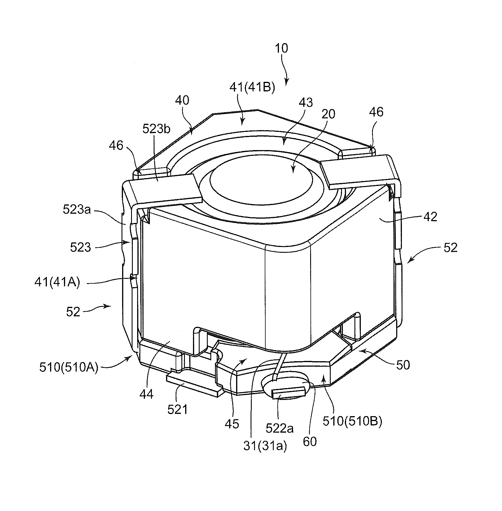
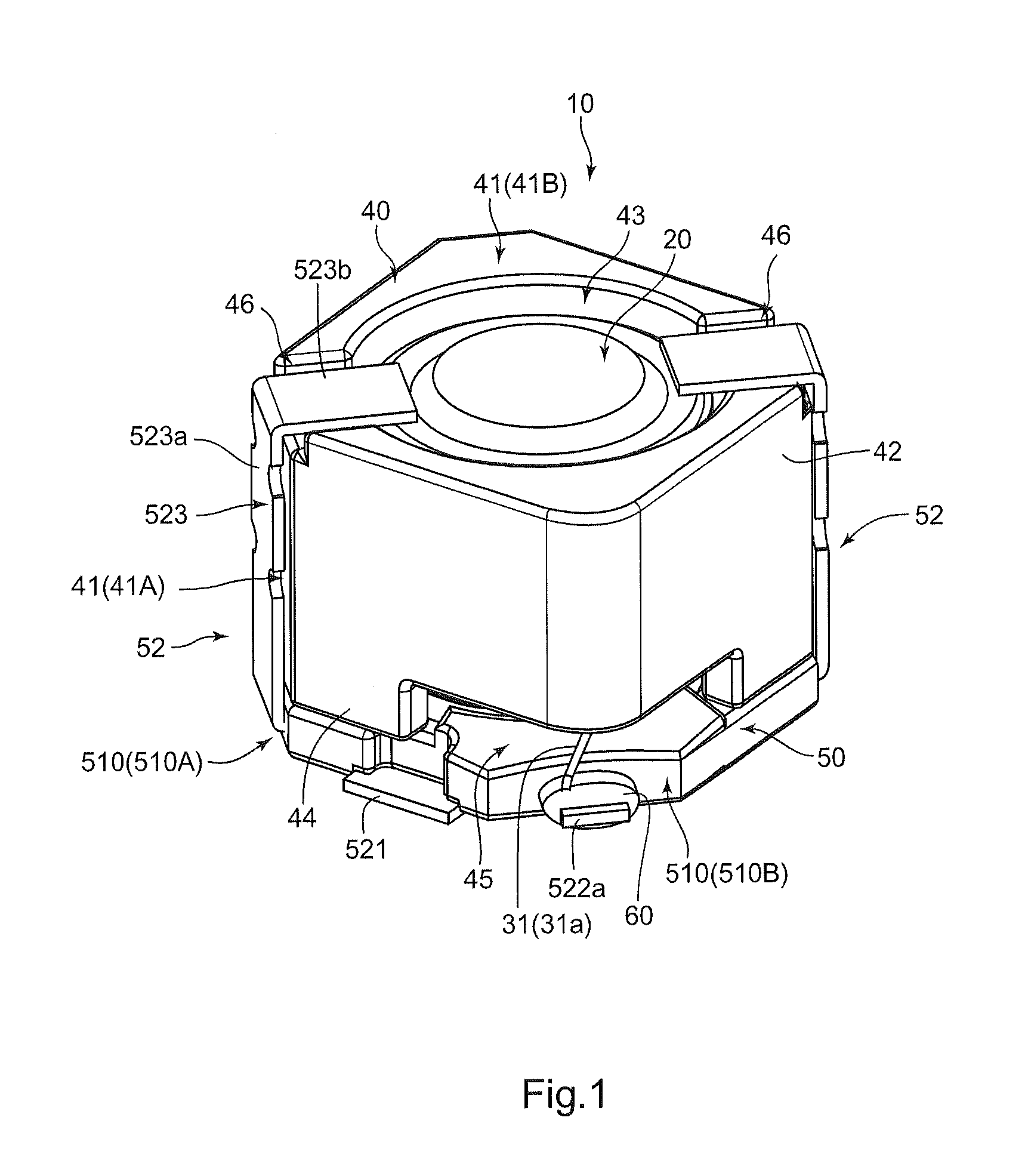
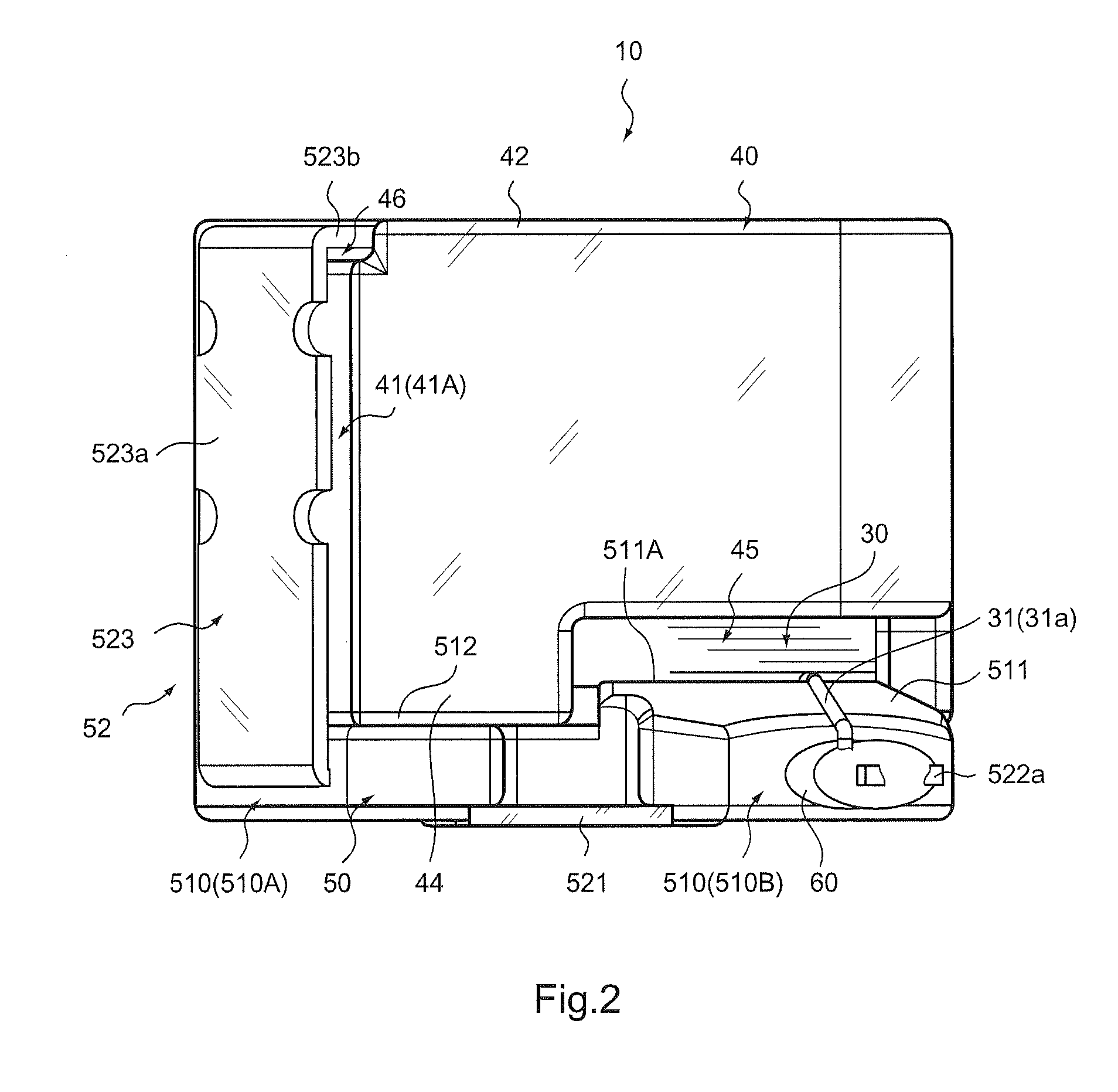
[0030]Hereinafter, a magnetic element 10 according to one embodiment of the present invention will be described based on FIG. 1 to FIG. 14.

[0031]As illustrated in FIG. 1 to FIG. 9 and the like, the magnetic element 10 of this embodiment includes a drum core 20, a coil 30, a ring core 40, and a base shaped body 50. Among them, the drum core 20 corresponds to a first core member. This drum core 20 has, as illustrated in FIG. 6, FIG. 8 and FIG. 9 and the like, an upper flange part 21, a columnar part 22, and a lower flange part 23. The upper flange part 21, the columnar part 22, and the lower flange part 23 are provided to have a circular planar shape. In this embodiment, the upper flange part 21 of the drum core 20 is provided to be equal in diameter to the lower flange part 23. Further, in this embodiment, the upper flange part 21 and the lower flange part 23 are provided to have a same thickness dimension of a flange part.

[0032]Note that the lower flange part 23 corresponds to one f...


PUM

PropertyMeasurementUnit
angleaaaaaaaaaa
magneticaaaaaaaaaa
shapeaaaaaaaaaa

Abstract

A magnetic element may include a first core member, a second core member facing the first core member along an entire outer periphery thereof, a coil, and a base shaped body on which the first core member and the second core member are placed. The base shaped body is provided with a base member and a terminal member, and the terminal member is provided with a binding terminal part, which projects outward in a first corner part of the base member and projects from the base member on a side lower than a portion of a winding frame part side of one flange part. The second core member is provided with a cutout part at a portion corresponding to the first corner part of the base member for allowing insertion of an end drawn out from the winding frame part in a state of not contacting the second core member.

Description

BACKGROUND OF THE INVENTION[0001]1. Field of the Invention[0002]The present invention relates to a magnetic element.[0003]2. Description of the Related Art[0004]Among magnetic elements, there exists a type having a drum core, a spacer, and a ring core as described in Patent Document 1. In such a structure disclosed in Patent Document 1, a terminal is disposed on an outer peripheral side of the ring core, and an end of a lead wire is soldered to this terminal.[0005][Patent Document 1] Japanese Patent Application Laid-open No. 2008-108944[0006]The magnetic element disclosed in Patent Document 1 has a structure in which the end of the lead wire contacts an edge existing in a surrounding area of a drawing portion of a large flange part, and moreover, the end of the lead wire contacts edges of the spacer and the ring core. However, when the end of the lead wire contacts edges of such a core and a spacer, the lead wire may break especially when the magnetic element is used in an environme...

Claims


Application Information

Patent Timeline
Patent Type & Authority Patents(United States)
IPC IPC(8): H01F17/04H01F27/06H01F27/02H01F27/29H01F27/24
CPCH01F27/306H01F17/045H01F27/292
Inventor NISHINO, TATSUMIONO, MASAHIKO
Owner SUMIDA CORP
Why Eureka
Try Eureka