Cabinet lifting device

a lifting device and cabinet technology, applied in the field of lifting devices, can solve the problems of increasing the labor cost of such installation, the confines of the cabinet enclosure, and the difficulty of one person achieving the installation of cabinets and the like in the kitchen, so as to achieve convenient change of direction, prevent the effect of moving sections, and effectively increase the applied for

Inactive Publication Date: 2014-06-03
FOSTER ROY
View PDF5 Cites 7 Cited by
  • Summary
  • Abstract
  • Description
  • Claims
  • Application Information

AI Technical Summary

Benefits of technology

[0019]The pulley mechanism further includes a support bracket advantageously connected to the upper end portions of the plurality of first support members and to the movable section respectively. An elongated flexible rope and a plurality of sheaves is connected to the plurality of first support members. Such a plurality of sheaves has a grooved rim for receiving the rope therealong for conveniently changing a direction and a point of application of a pulling force, and in a predetermined combination to effectively increase the applied force for conveniently lifting a cabinet positioned onto the movable section. A cranking mechanism operably winds the rope in a predetermined direction.
[0020]Such a cranking mechanism includes an elongated shaft that has opposed end portions effectively secured to the plurality of side panels, and extends outwardly from one of the plurality of side panels respectively. The rope has opposed end portions effectively secured to the shaft and the upper end of one of the elongated supports respectively. A gear has a serrated outer surface and is connected to the shaft. A crank handle is connected to the shaft and effectively causes the gear to rotate in a predetermined direction as the handle is radially moved about the shaft. A pawl has a first end portion pivotally connected to the one side panel and further has a second end portion selectively engageable with the gear for advantageously permitting the gear and the shaft to rotate in only one direction, and thereby effectively prevent the moveable section from unexpectedly moving downwardly after a cabinet is placed thereon.

Problems solved by technology

The installation of cabinets and the like within kitchens is difficult for one person to accomplish in view of the size of the cabinets and the confines of the kitchen enclosure.
The use of a helper increases the labor cost of such installation.
However, there are several drawbacks to using another person as helper.
For example, it is very difficult for a helper to hold a cabinet steady in the selected or proper position.
These approaches are usually clumsy, unsatisfactory and dangerous.
In addition, lifting cabinets can cause back injuries and other medical problems.
A further problem associated with positioning such cabinets is the requirement to level and shim the cabinets prior to final installation.
The use of conventional vertical lifting devices, per se, does not readily allow such leveling and horizontal positioning of the cabinets.
Unfortunately, this prior art example requires the use of a power drill to raise and the lower the platform of the device.
Unfortunately, this prior art example does not provide a suitably stable and wheeled base for use with heavy cabinets and hardware.

Method used


Image

  • Cabinet lifting device
  • Cabinet lifting device
  • Cabinet lifting device

Examples


Embodiment Construction

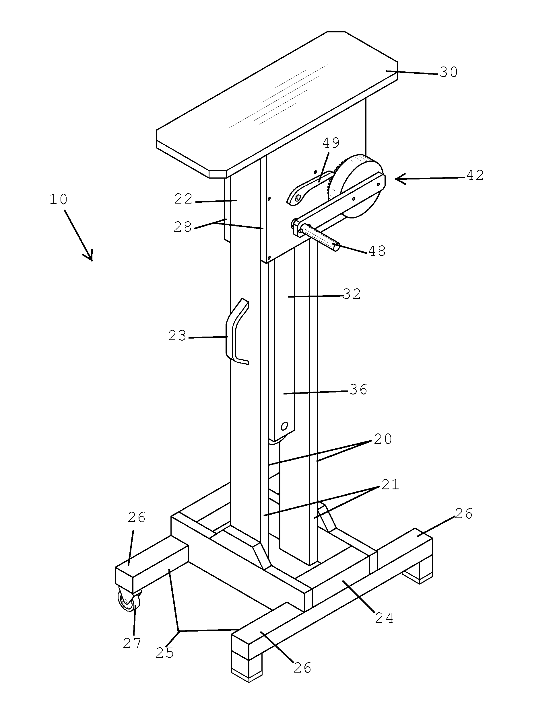
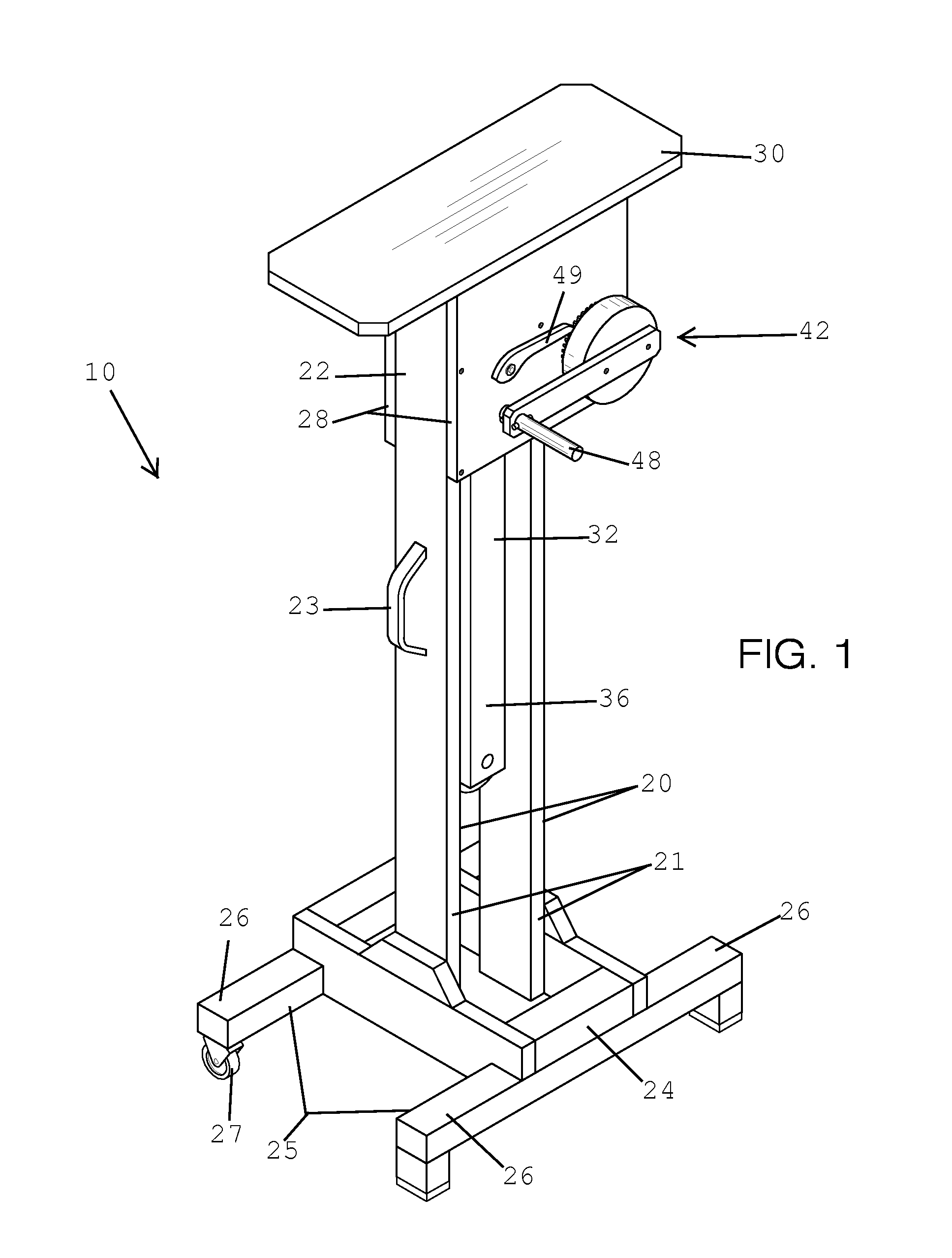
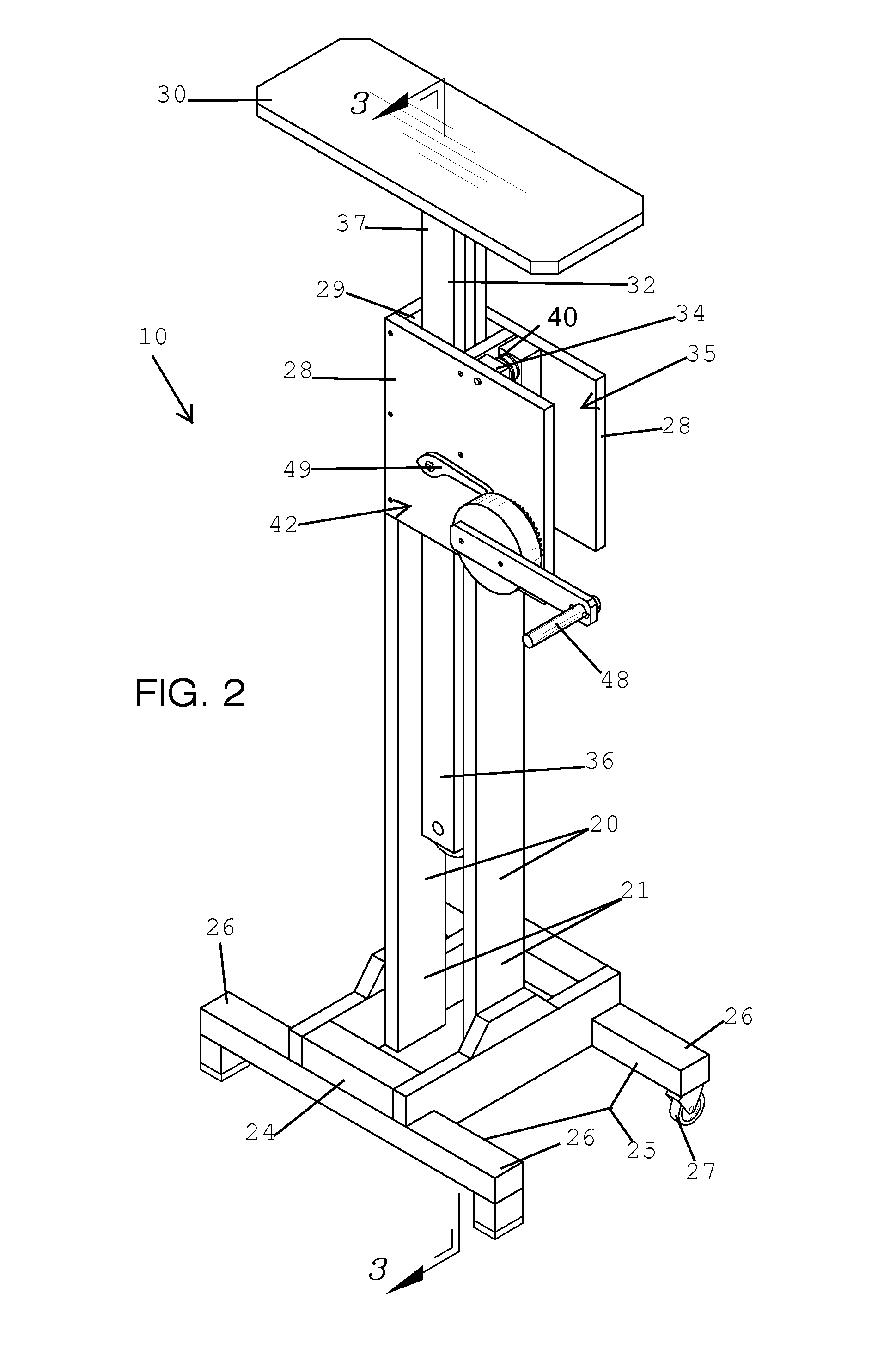
[0035]The present invention will now be described more fully hereinafter with reference to the accompanying drawings, in which a preferred embodiment of the invention is shown. This invention may, however, be embodied in many different forms and should not be construed as limited to the embodiment set forth herein. Rather, this embodiment is provided so that this application will be thorough and complete, and will fully convey the true scope of the invention to those skilled in the art. Like numbers refer to like elements throughout the figures.

[0036]The illustrations of the embodiments described herein are intended to provide a general understanding of the structure of the various embodiments. The illustrations are not intended to serve as a complete description of all of the elements and features of apparatus and systems that utilize the structures or methods described herein. Many other embodiments may be apparent to those of skill in the art upon reviewing the disclosure. Other ...


PUM


Abstract

A lifting and supporting device includes elongated supports. One support has a handle attached thereto. A base section has rectilinear support arms attached thereto. The arms are arranged in parallel transverse to a longitudinal length of the base section. The base section is secured to the lower end portions of the supports. Side panels are secured to the upper end portions of the supports. A moveable section is disposed medially of the side panels. A pulley mechanism lifts the movable section in a vertical direction between raised and lowered positions. The pulley mechanism is partially disposed within the cavity and is anchored to the moveable section and the side panels. The pulley mechanism includes at least five pulleys for to decrease the applied force for lifting a cabinet on the movable section. A pressure plate is used to maintain the movable section in a static position during non-operating conditions.

Description

CROSS REFERENCE TO RELATED APPLICATIONS[0001]This application is a continuation-in-part application of U.S. patent application Ser. No. 11 / 607,939, filed Dec. 4, 2006, the entire disclosure of which is incorporated herein by reference.STATEMENT REGARDING FEDERALLY SPONSORED RESEARCH OR DEVELOPMENT[0002]Not Applicable.REFERENCE TO A MICROFICHE APPENDIX[0003]Not Applicable.BACKGROUND OF THE INVENTION[0004]1. Technical Field[0005]This invention relates to a lifting device and, more particularly, to a cabinet lifting device for assisting an operator to maintain a cabinet steady during an installation process.[0006]2. Prior Art[0007]The installation of cabinets and the like within kitchens is difficult for one person to accomplish in view of the size of the cabinets and the confines of the kitchen enclosure. Normally, when installing an item such as a cabinet or ceiling frame, it is necessary for a helper to lift the cabinet in place against a wall or ceiling while the item is secured to...

Claims


Application Information

Patent Timeline
Patent Type & Authority Patents(United States)
IPC IPC(8): B66F7/02
CPCB66F3/00A47B96/00B66F7/02
Inventor FOSTER, ROY
Owner FOSTER ROY
Why Eureka
Try Eureka