
Internal antenna supporting wideband impedance matching

a technology of impedance matching and antenna, applied in the field of antenna, can solve the problems of poor sar (specific absorption rate), difficult to provide an esthetic appearance and an external design, and achieve the effect of efficient utilization of spa

Inactive Publication Date: 2014-06-03
ACE TECH
View PDF8 Cites 3 Cited by
  • Summary
  • Abstract
  • Description
  • Claims
  • Application Information

AI Technical Summary

Benefits of technology

[0022]An embodiment of the present invention offers the advantages of overcoming the narrow band problem of a planar inverted-F antenna, and of allowing more efficient utilization of space in an internal antenna.

Problems solved by technology

Such an antenna has the advantage of high profits, but due to its non-directivity, the SAR (specific absorption rate)—the standard for the level of harmfulness of electromagnetic waves to the human body—is not good.
Also, as a helical antenna is constructed as protruding out of a terminal, it is not easy to provide an esthetic appearance and an external design suitable to portability of the terminal, and no study has been done on an internal structure with regards to this.
However, an inverted-F antenna has the problem of having a narrow frequency band width.
However, there was the problem of the size of the antenna being large, as a separate impedance matching part for such coupling matching and coupling feeding occupied a comparatively large space.

Method used


Image

  • Internal antenna supporting wideband impedance matching
  • Internal antenna supporting wideband impedance matching
  • Internal antenna supporting wideband impedance matching

Examples


Embodiment Construction

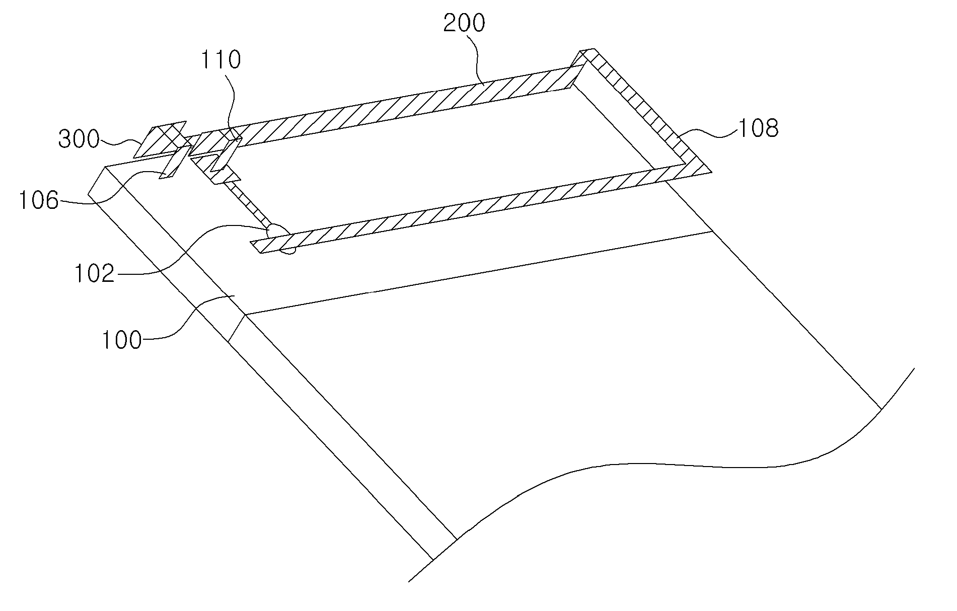
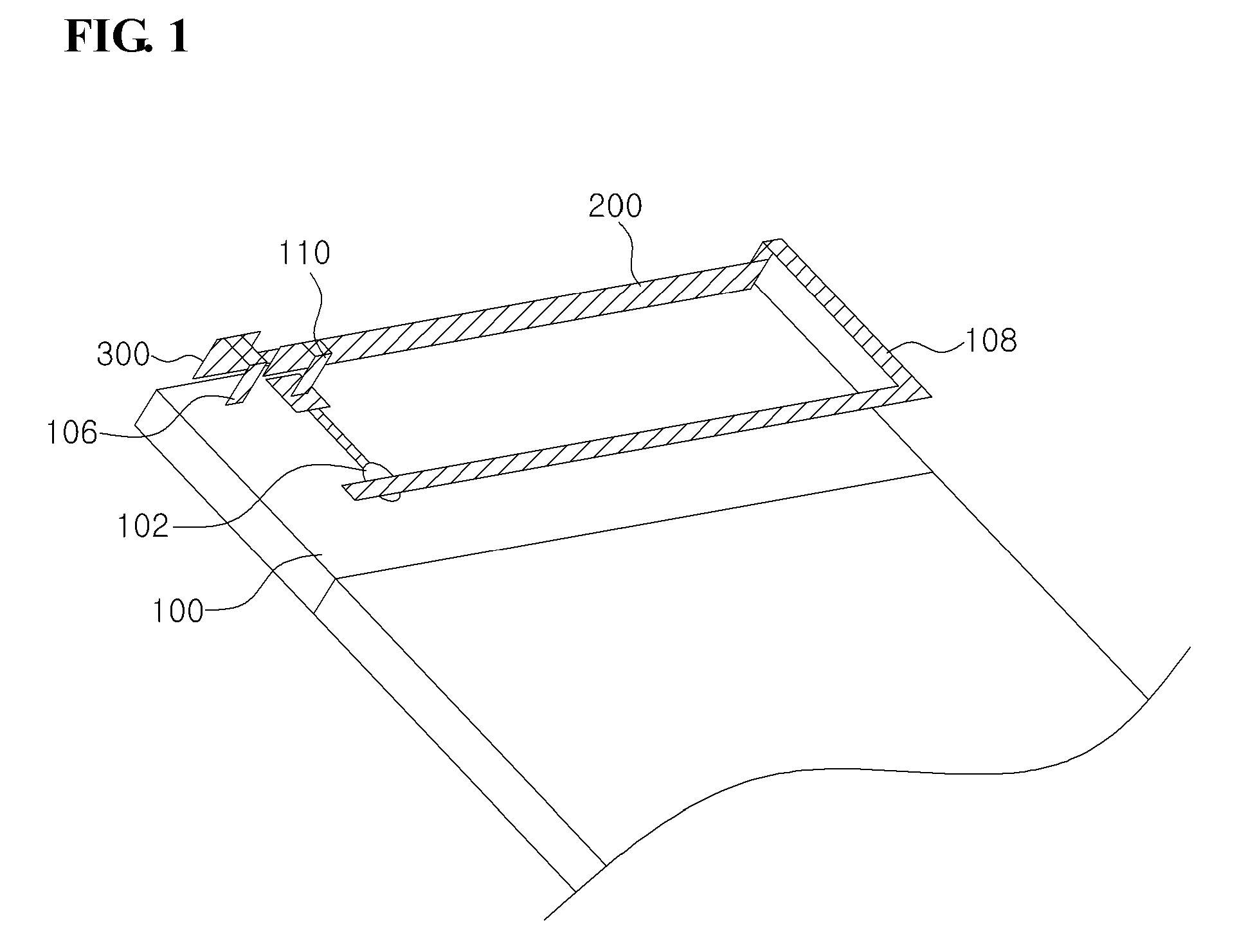
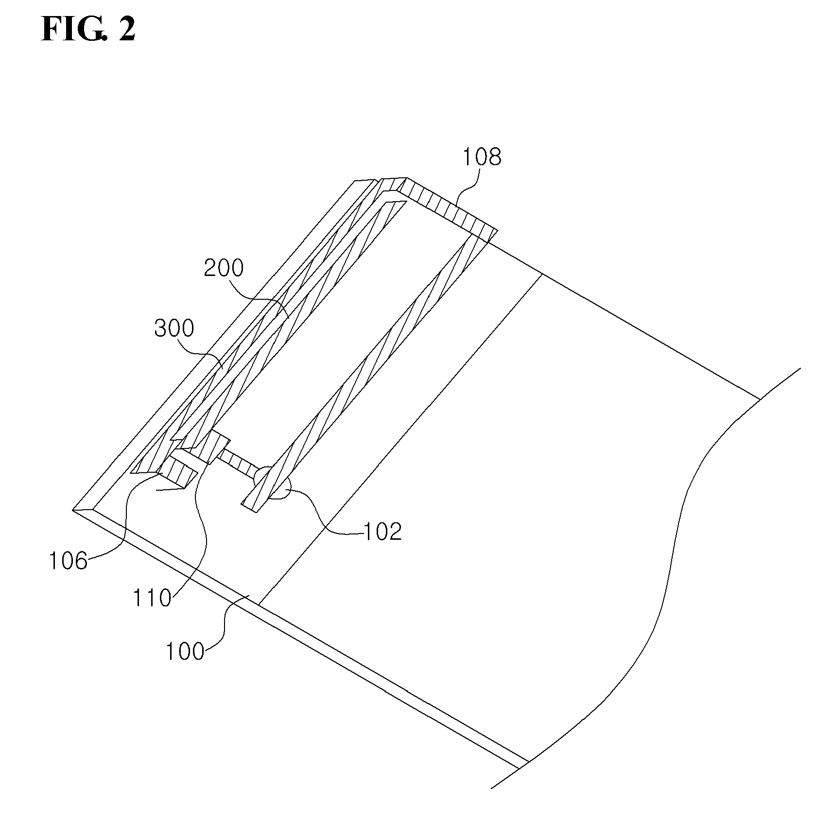
[0032]An internal antenna providing impedance matching for a wide band according to an embodiment of the invention will be described below in more detail with reference to the accompanying drawings.

[0033]An internal antenna providing impedance matching for a wide band according to an embodiment of the invention may be implemented with the use of a carrier, but for the sake of ease of explanation, first a description will be given of an antenna having a structure without a carrier with reference to FIGS. 1 to 3, and then later a description will be given of a structure implemented with a carrier.

[0034]FIG. 1 is a drawing illustrating a perspective view of an internal antenna for a wide band according to an embodiment of the present invention; FIG. 2 is a drawing illustrating a perspective view of the internal antenna for a wide band according to an embodiment of the present invention seen from another direction; and FIG. 3 is a drawing illustrating a plan view of the internal antenna...


PUM


Abstract

An internal antenna providing impedance matching for a wide band is disclosed. The disclosed antenna may include: a substrate; an impedance matching / feeding unit comprising a feeding member, separated from the substrate at a designated distance, configured to receive RF signals, and of a designated length in a first direction, and a ground member, separated from the substrate at a designated distance, separated from the feeding member at a designated in a second direction perpendicular to the first direction, and of a designated length in the first direction; and a radiator extending from the ground member; wherein the impedance matching / feeding unit performs impedance matching by way of coupling between the feeding member and the ground member, and the radiator receives coupling feeding from the feeding member. The disclosed antenna has the advantages of overcoming the narrow band problem of a planar inverted-F antenna, and of allowing more efficient utilization of space in an internal antenna.

Description

CROSS-REFERENCES TO RELATED APPLICATIONS[0001]This application is a U.S. national phase application, pursuant to 35 U.S.C. §371, of PCT / KR2009 / 01599, filed Mar. 30, 2009, designating the United States, which claims priority to Korean Application No. 10-2008-0125477, filed Dec. 10, 2008. The entire contents of the aforementioned patent applications are incorporated herein by this reference.TECHNICAL FIELD[0002]The present invention relates to an antenna, more particularly to an internal antenna providing impedance matching for a wide band.BACKGROUND ART[0003]Recently there has been a demand for the ability to receive mobile communication services of different frequency bands through one mobile communication terminal, even as mobile communication terminals become smaller and lighter. There is a demand for terminals that are able to use signals of multiple bands simultaneously as necessary, for mobile communication services using a variety of frequency bands such as, for example, the C...

Claims


Application Information

Patent Timeline
Patent Type & Authority Patents(United States)
IPC IPC(8): H01Q1/48
CPCH01Q1/243H01Q9/0421H01Q1/38H01Q9/0457H01Q5/50H01Q1/24
Inventor KIM, BYONG-NAM
Owner ACE TECH
Learn More