Pointing device comprising a light control part and electronic apparatus comprising an input device
a technology of electronic apparatus and control part, which is applied in the direction of optical radiation measurement, pulse technique, instruments, etc., can solve the problems of difficult to employ input using the keypad as direction keys for portable information terminals, complicated operation of portable information terminals, and inability to perform desired operations easily, etc., to achieve the effect of preventing malfunction, reducing power consumption, and improving detection accuracy
- Summary
- Abstract
- Description
- Claims
- Application Information
AI Technical Summary
Benefits of technology
Problems solved by technology
Method used
Image
Examples
embodiment 1
[0154]An embodiment of the present invention will be explained with reference to drawings.
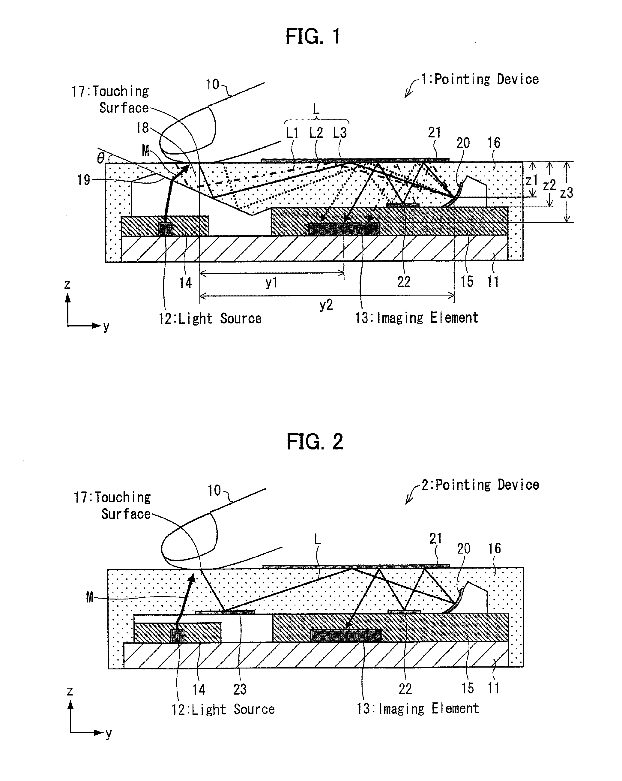
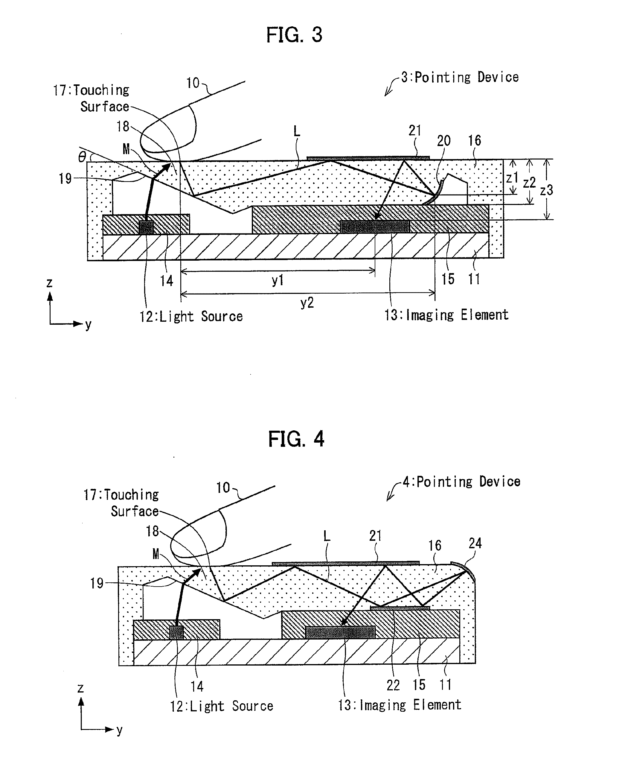
[0155]FIG. 8 is a cross sectional drawing illustrating an example of a configuration of the pointing device 40 in accordance with the present embodiment.
[0156]As illustrated in FIG. 8, the pointing device 40 in accordance with the present embodiment includes first light control means 31 in addition to the configuration of the pointing device 1 shown in FIG. 1. In the pointing device 40 of the present embodiment, the light source 12 is a light emitting diode 12a.
[0157]The first light control means 31 is an electrode made of a metal film provided on a top surface of the light emitting diode 12a in such a manner as to be on and around the center of the top surface. Unlike a general metal electrode, the first light control means 31 occupies 78% of the area of the upper surface of the light emitting diode 12a in order to yield a light control effect. Therefore, the first light control means 31 bloc...
embodiment 2
[0170]The following explains another embodiment of the present invention with reference to drawings.
[0171]FIG. 13 is a cross sectional drawing showing a configuration example of the pointing device 41 of the present embodiment. FIG. 14 is an enlarged cross sectional drawing showing an illuminating optical system including a light emitting diode 12a and a touching surface 17 in a pointing device 41 in FIG. 13.
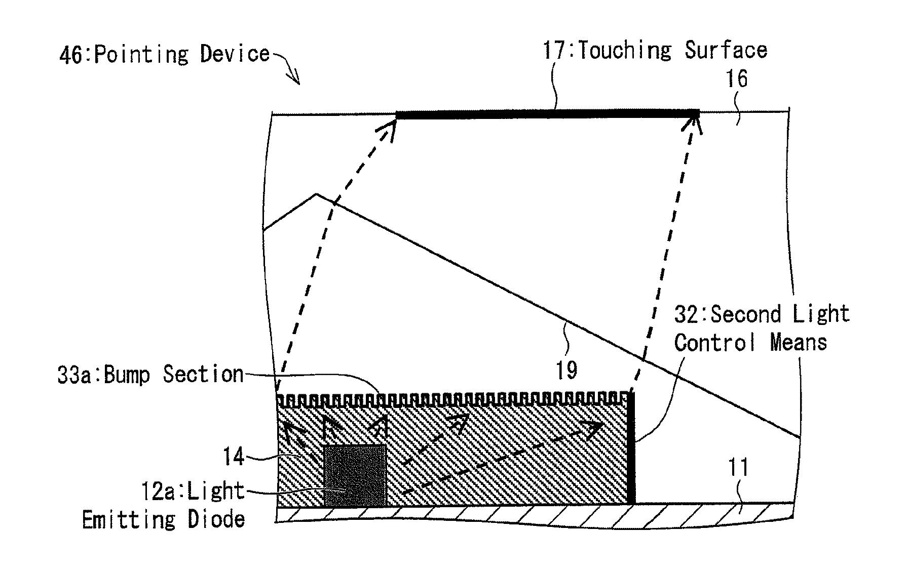
[0172]As shown in FIGS. 13 and 14, the pointing device 41 of the present embodiment includes second light control means 32 in addition to the configuration of the pointing device 40 of FIG. 8 explained in Embodiment 1.
[0173]The second light control means 32 blocks light emitted from the light emitting diode 12a and reaching the imaging element 13. In other words, the second light control means 32 blocks light that does not contribute to illumination of the touching surface 17 out of light emitted from the light emitting diode 12a. The second light control means 32 is provided on...
embodiment 3
[0179]FIG. 15 is a cross sectional drawing showing a configuration example of a pointing device 42 of the present embodiment, and showing an illuminating optical system including the light emitting diode 12a and the touching surface 17 in an enlarged manner.
[0180]The pointing device 41 shown in FIG. 13 explained in Embodiment 2 is designed such that the first light control means 31 is provided at only one position. Alternatively, the first light control means 31 may be provided at plural positions if necessary. For example, as shown in FIG. 15, the pointing device 42 of the present embodiment is designed such that the resin mold section 14 is provided with first light control means 31a and 31b.
[0181]The first light control means 31a and 31b are provided on the top surface of the resin mold section 14 and at the same time on a light path from the light emitting diode 12a to the touching surface 17. Further, in order to block light with particularly high light intensity, the first li...
PUM
 Abstract
Description
Claims
Application Information
 - R&D
- Intellectual Property
- Life Sciences
- Materials
- Tech Scout
- Unparalleled Data Quality
- Higher Quality Content
- 60% Fewer Hallucinations
Browse by: Latest US Patents, China's latest patents, Technical Efficacy Thesaurus, Application Domain, Technology Topic, Popular Technical Reports.
© 2025 PatSnap. All rights reserved.Legal|Privacy policy|Modern Slavery Act Transparency Statement|Sitemap|About US| Contact US: help@patsnap.com


