Systems and methods for coordinated editing of seismic data in dual model
What is AI technical title?
AI technical title is built by Patsnap AI team. It summarizes the technical point description of the patent document.
a dual-model, seismic data technology, applied in the direction of instruments, details involving 3d image data, image enhancement, etc., can solve the problem of difficult implementation of edits
Active Publication Date: 2014-06-03
ASPEN PARADIGM HLDG LLC
View PDF77 Cites 85 Cited by
Summary
Abstract
Description
Claims
Application Information
AI Technical Summary
This helps you quickly interpret patents by identifying the three key elements:
Problems solved by technology
Method used
Benefits of technology
Benefits of technology
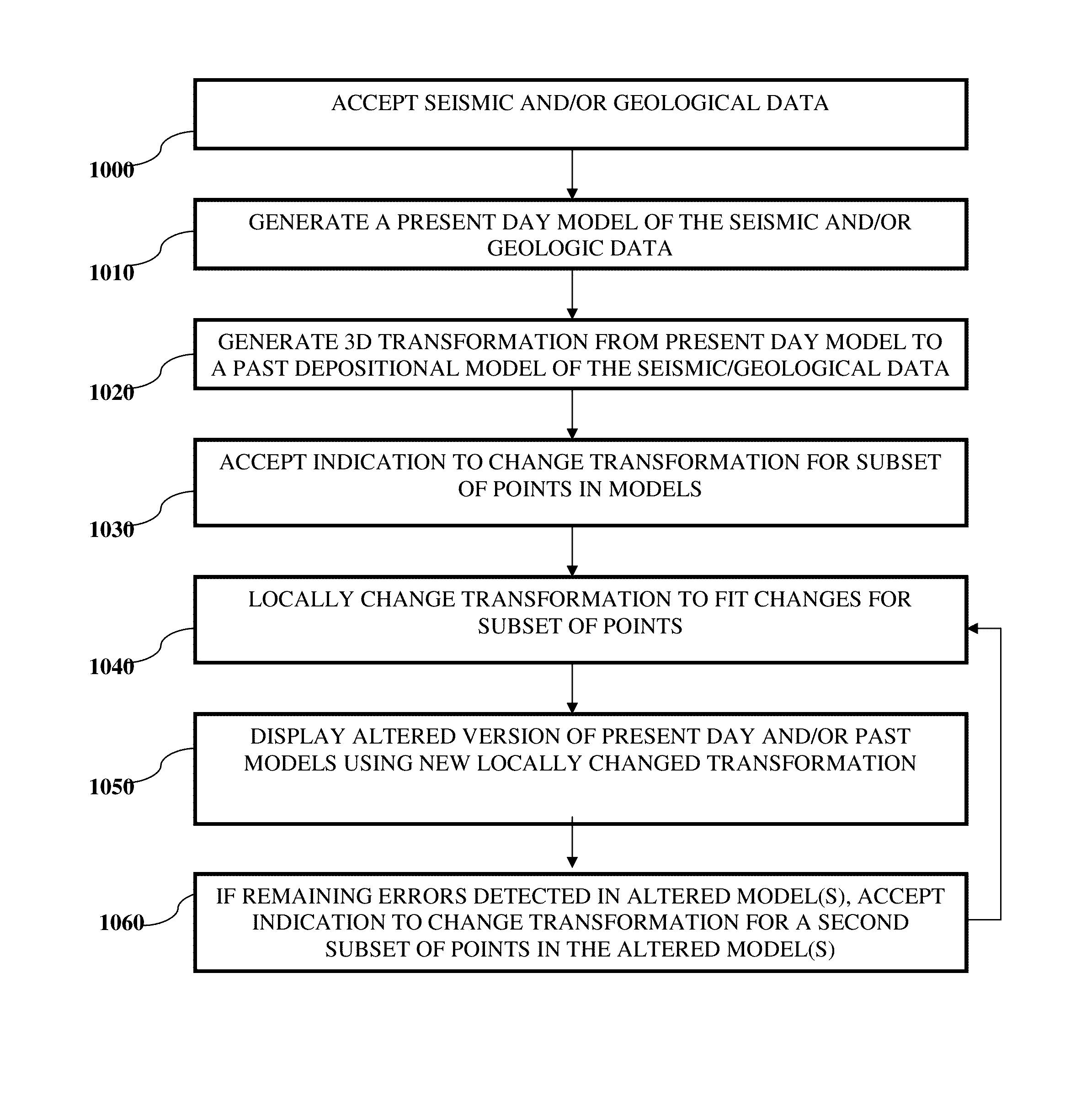
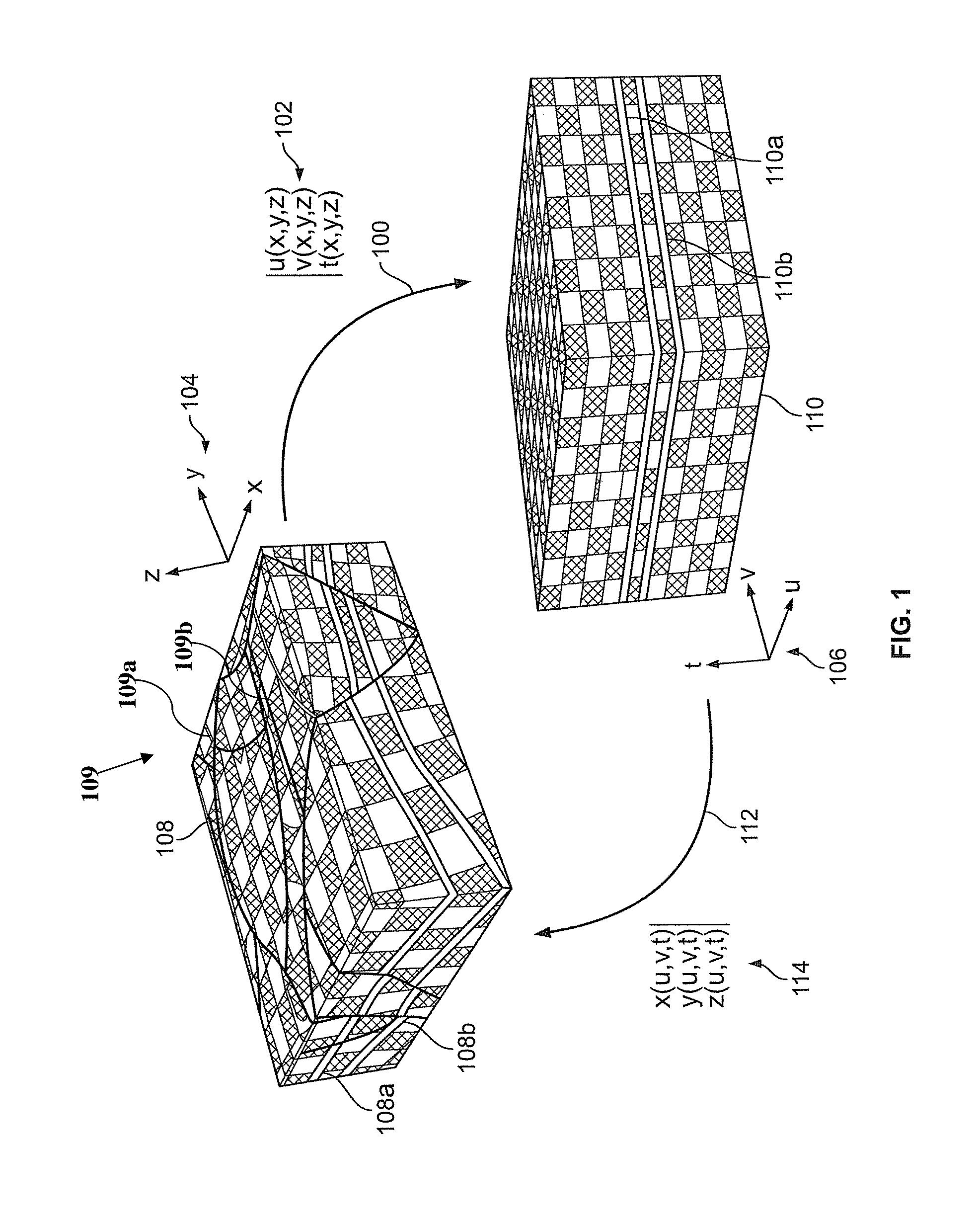
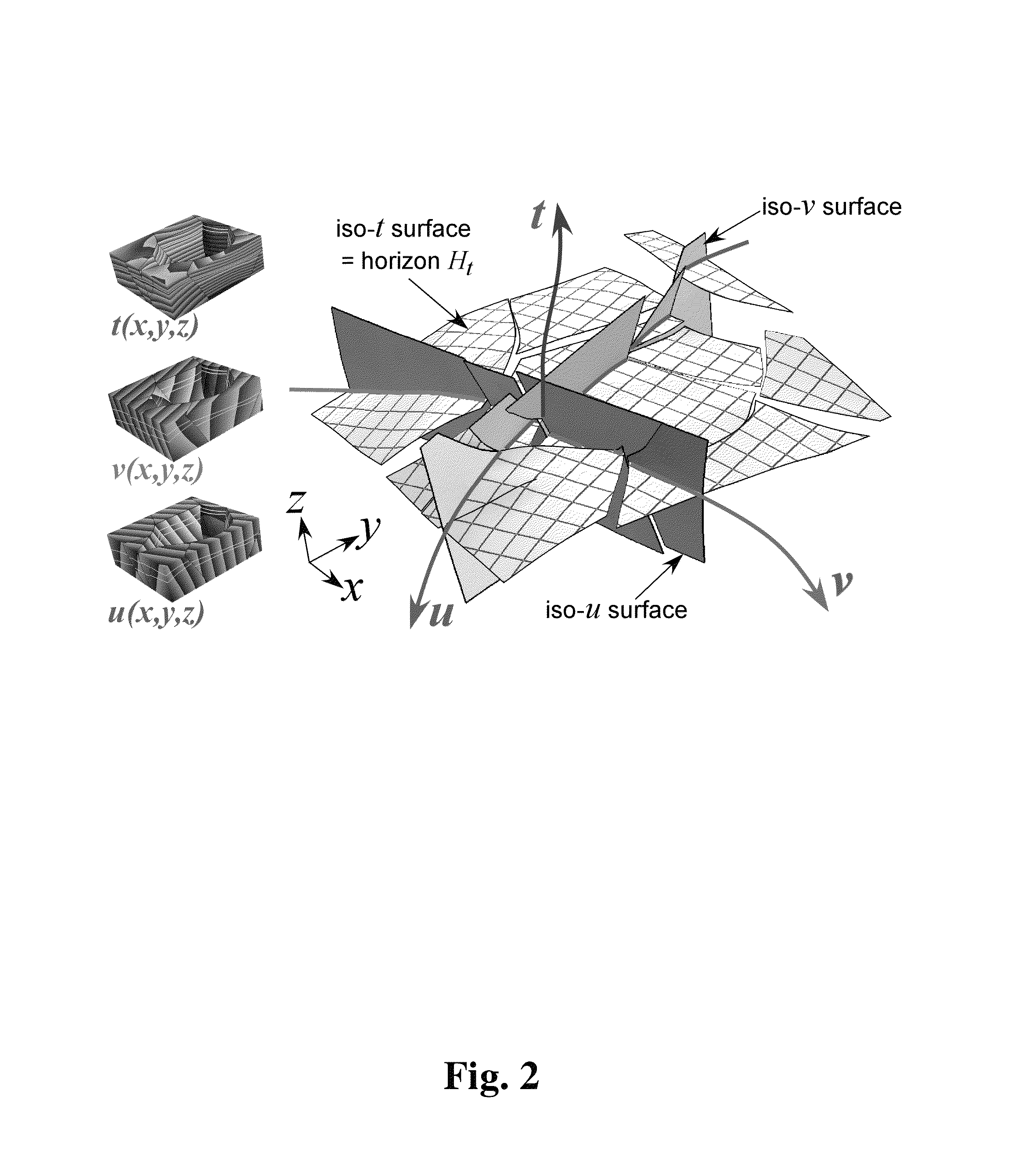
The invention provides a system and method for modeling the structure of geological terrains, including faults, by using seismic data and geological models. The system allows users to modify the geometry and properties of geological structures by incrementally altering horizons and faults. The models generated can include both the geometry and properties of the structures. The system also allows users to interact with the models, editing the location or physical properties of points in the models, and automatically updating the models to reflect changes made to the points. The invention also provides a global transformation that can be used to relate different models of the same physical geological structures. This transformation can facilitate the editing and display of the models. Overall, the invention provides a more accurate and efficient tool for exploring and modeling underground geological structures.
Problems solved by technology
In this way, a user may interact or edit a depositional time model (where structures and properties are uniformly distributed) and the user may view the corresponding edits implemented in the present day complex faulted model, where such edits would be difficult to implement, e.g., particularly across faults.
Method used
Image
Click on the blue label to locate the original text in one second.
Reading with bidirectional positioning of images and text.
Examples
first embodiment
[0180]In a first embodiment, for a given seed point or a sampling point (s0) extracted, e.g., by a user, from H(tnew) having coordinates (x0, y0, z0) in the G space 104, a new sampling point (s) may be selected, e.g., by a user via user input device 965 of FIG. 9, in the neighborhood of (s0) to be added to SH(tnew), for example, as follows:[0181]1. Intervals or step sizes sx and sy may be selected in the x and y directions, respectively, of seismic cube grid SG 126.[0182]2. A point (q) neighboring (s0) with coordinates (x0+sx, y0+sy, z0) may be selected, e.g., by a user via user input device 965 of FIG. 9.[0183]3. Seismic windows W(x0, y0, z0) and W(x0+sx, y0+sy, z0) may be extracted from the seismic cube grid SG 126, e.g., automatically by processor 940 of FIG. 9.[0184]4. The seismic window W(x0, y0, z0) of point s0 may be compared to the seismic window W(x0+sx, y0+sy, z0) of point (q) to determine the optimal value of (dz) such that (s) with coordinates (x0+sx, y0+sy, z0+dz) best ...
second embodiment
[0188]In a second embodiment, for a given seed point or a sampling point (s0) extracted from SH(tnew) having coordinates (x0, y0, z0) in the G space 104, a new sampling point (s) may be selected, e.g., in the neighborhood of (s0) to be added to SH(tnew), taking into account the current geological-time function t(x, y, z), for example, as follows:[0189]1. Intervals or step sizes sx and sy may be selected in the x and y directions, respectively, of seismic cube grid SG 126.[0190]2. A value (znew) may be determined so that t(x0+sx, y0+sy, znew) is equal to (tnew).[0191]3. Seismic windows W(x0, y0, z0) and W(x0+sx, y0+sy, znew) may be extracted from the seismic cube grid SG 126.[0192]4. The seismic window W(x0, y0, z0) of point s0 may be compared to the seismic window W(x0+sx, y0+sy, znew) to determine the optimal value of (dz) such that the point (s) with coordinates (x0+sx, y0+sy, znew+dz) best correlates with (s0).[0193]5. Add (s) to the refined set of sampling points SH(tnew).[0194]...
PUM
Abstract
A system and method may model physical geological structures. Seismic and geologic data may be accepted. A three-dimensional (3D) transformation may be generated between a 3D present day model having points representing present locations of the physical geological structures and a 3D past depositional model having points representing locations where the physical geological structures were originally deposited. An indication may be accepted to locally change the 3D transformation for a subset of sampling points in a first model of the models. The 3D transformation may be locally changed to fit the updated subset of sampling points. A locally altered or updated version of the first model and, e.g., second model, may be displayed where local changes to the first model are defined by the locally changed 3D transformation. The transformation may also be used to extract geobodies in the past depositional model.
Description
CROSS-REFERENCE TO RELATED APPLICATIONS[0001]This application claims the benefit of prior U.S. Provisional Application Ser. No. 61 / 254,438, filed Oct. 23, 2009, which is incorporated by reference herein in its entirety.FIELD OF THE INVENTION[0002]The invention pertains to the general field of modeling stratified terrains in the subsurface.[0003]The invention pertains to generating a first present day model representing stratified terrains and generating a second corresponding depositional model representing the stratified terrains at the geological-time at which they were originally deposited within the Earth.BACKGROUND OF THE INVENTION[0004]Erosion and tectonic activity through time transform an initially uniform stratified terrain composed of a continuous stack of level surfaces to a terrain fractured by faults forming discontinuities across the originally continuous horizons. Accordingly, to model the subsurface at the original time of deposition from seismic data (e.g., associat...
Claims
Application Information
Patent Timeline
Application Date:The date an application was filed.
Publication Date:The date a patent or application was officially published.
First Publication Date:The earliest publication date of a patent with the same application number.
Issue Date:Publication date of the patent grant document.
PCT Entry Date:The Entry date of PCT National Phase.
Estimated Expiry Date:The statutory expiry date of a patent right according to the Patent Law, and it is the longest term of protection that the patent right can achieve without the termination of the patent right due to other reasons(Term extension factor has been taken into account ).
Invalid Date:Actual expiry date is based on effective date or publication date of legal transaction data of invalid patent.

