Method for operating a leveling device of a vehicle

Inactive Publication Date: 2014-06-10
KNORR-BREMSE SYST FUER NUTZFAHRZEUGE GMBH
View PDF15 Cites 0 Cited by
  • Summary
  • Abstract
  • Description
  • Claims
  • Application Information

AI Technical Summary

Benefits of technology

[0009]By contrast, it is an object of the exemplary embodiments and/or exemplary methods of the present invention to provide a method for oper

Problems solved by technology

It is believed to be understood that wear of the corrugated bellows or rolling bellows constitutes a problem, and that in particular tears in the bellows can occur as a result of wear.
Since an exchange of the corrugated bellows or rolling bellows must be performed in a workshop, the vehicle is no longer availa

Method used


Image

  • Method for operating a leveling device of a vehicle
  • Method for operating a leveling device of a vehicle

Examples


Embodiment Construction

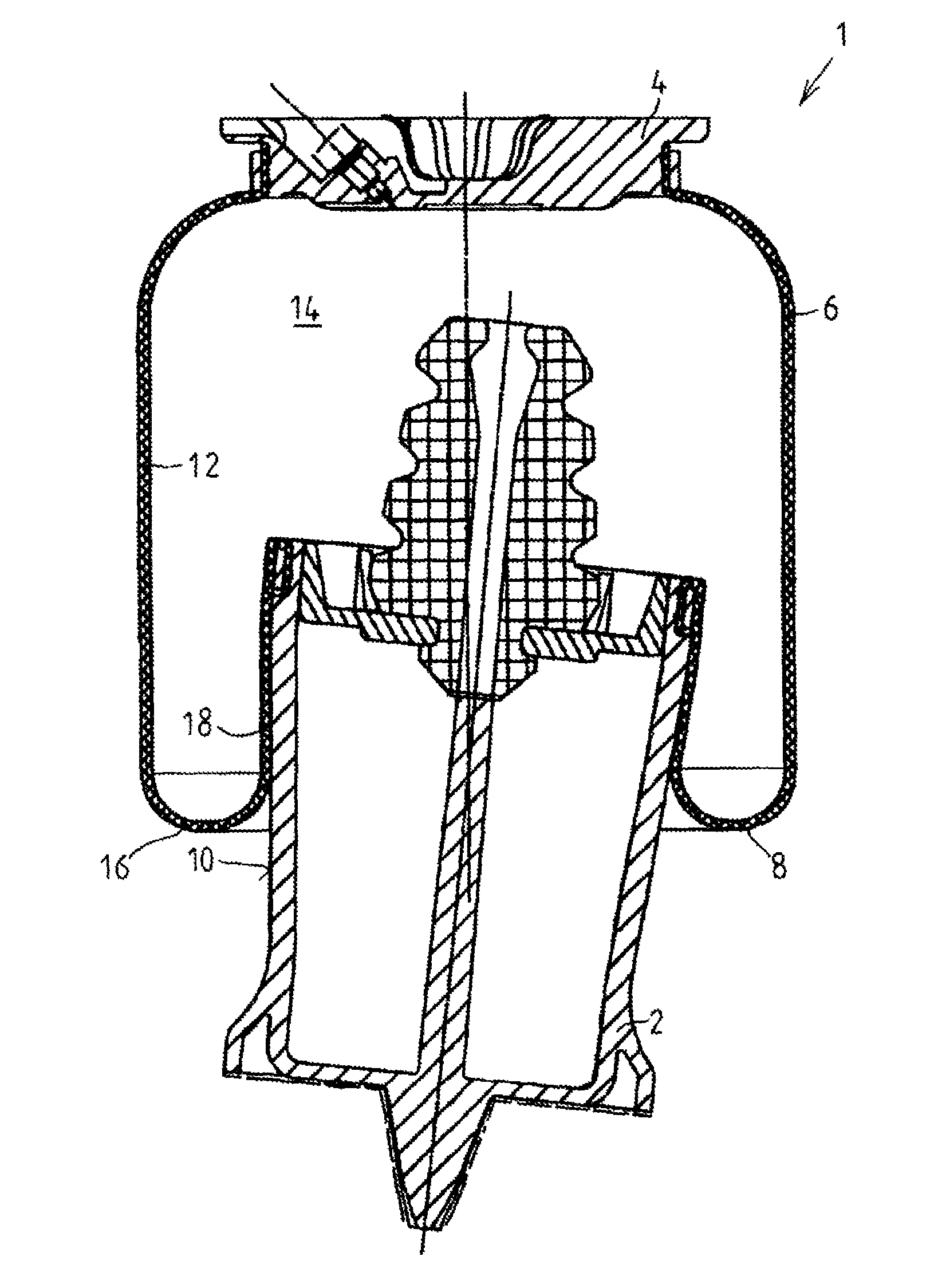
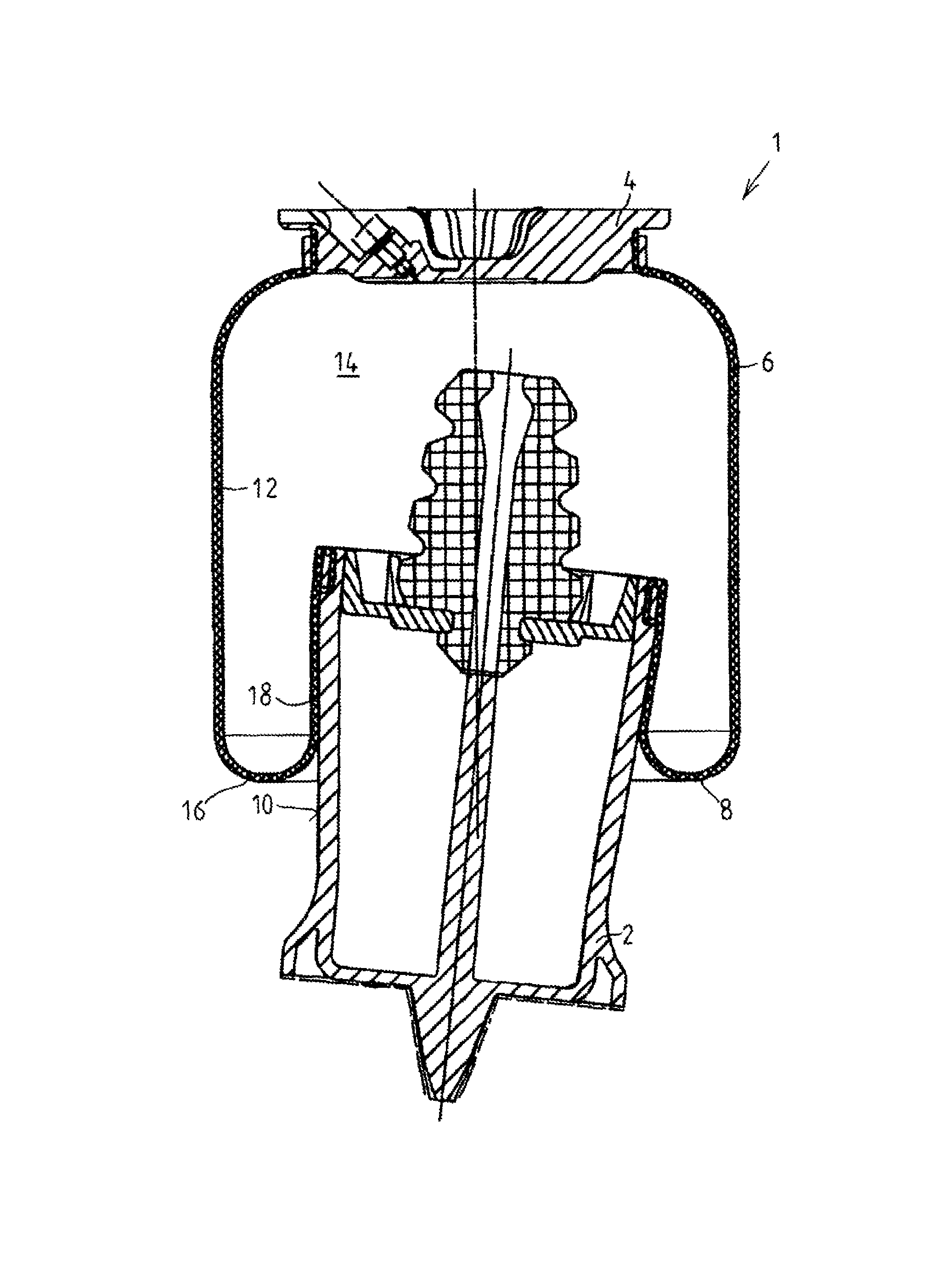
[0022]The FIGURE shows an air spring 1 such as is believed to be known, having a rolling piston 2, a bellows cover 4 arranged at a vertical distance therefrom, and having a rolling bellows 6 composed of an elastomer material, which rolling bellows rolls with a roll fold 8 on a radially outer circumferential surface 10 of the rolling piston. As can be seen from the FIGURE, it is the case here that the roll fold 8 forms that portion of the bellows wall 12 which is subjected to the most intense deflection or bending, in this case through approximately 180 degrees.

[0023]Here, the rolling bellows 6 encloses, together with the bellows cover 4 and the rolling piston 2, an air chamber 14 which can be aerated and deaerated in order to adjust the ride height of a vehicle body in relation to a vehicle chassis.

[0024]Here, the air spring 1 is part of an air suspension device with ride height control, by which setting of or adjustment to a ride height setpoint value can be performed manually, for...


PUM


Abstract

A method for operating a ride height control device, which includes at least one air spring, of a vehicle body of a vehicle, by providing a setpoint ride height predefined for a journey, and by setting, at the beginning, during or immediately before the end of the journey, the ride height of the vehicle body at least once to a ride height which deviates from the setpoint ride height predefined for the journey.

Description

FIELD OF THE INVENTION[0001]The present invention relates to a method for operating a ride height control device of a vehicle body of a vehicle, which ride height control device includes at least one air spring.BACKGROUND INFORMATION[0002]The air volume of air springs is utilized, on the one hand, for the suspension of axles of motor vehicles. On the other hand, through the aeration and deaeration of air spring bellows by a valve device, such air springs permit ride height control, which offers advantages in particular for utility vehicles, if the vehicle body thereof must be set to the level of a ramp for example for loading purposes, or if a correction must be carried out in order to avoid an oblique position of the body owing to an eccentric load. Here, each wheel or else only each axle may be assigned an air bellows. Such a ride height control device is known for example from DE 10 2006 016 989 A1.[0003]As spring elements of the air springs, use is made of corrugated bellows or ...

Claims


Application Information

Patent Timeline
IPC IPC(8): B60G17/04
CPCB60G17/0161B60G17/0523B60G2202/152B60G2300/07B60G2400/821B60G2500/30B60G2800/164B60G17/016
Inventor NABER, THOMASBOUNDS, JOSEPH
Owner KNORR-BREMSE SYST FUER NUTZFAHRZEUGE GMBH
Why Eureka
Try Eureka