Method and device for overload detection in battery-operated devices having an electric motor

a battery-operated device and overload detection technology, which is applied in emergency protective circuit arrangements, parameter calibration/setting, instruments, etc., can solve problems such as excessive heating of the cell to only be detected, excessive rough protection, and the need for limiting curren

Inactive Publication Date: 2014-06-10
ROBERT BOSCH GMBH
View PDF4 Cites 0 Cited by
  • Summary
  • Abstract
  • Description
  • Claims
  • Application Information

AI Technical Summary

Benefits of technology

[0011]A further advantage of the method is that, consequently, for different uses of a device having an electric motor and the various, typical instances of current drain associated therewith, overly late detection of an impermissibly large temperature increase that has already occurred in the cell interior is prevented, but on the other hand, instances of temporarily high current drain are also rendered possible and not prevented by a temperature limit that is permanently set very low.
[0015]The method may allow the instantaneous load current to be reduced or interrupted as a countermeasure to a detected thermal overload. Other actions, such as warning the user by an optical or acoustic signal, or switching on a positive cooling system of the cells in the battery pack, as well as the combination of several actions, are also possible.
[0016]Starting out from different static temperature limits and / or different functions, example embodiments of the present invention may allow several variable temperature limits to be calculated; the load current only being interrupted in response to the highest calculated, variable temperature limit being exceeded, while in response to the lower, calculated variable temperature limits being exceeded, the load current being reduced, in each instance, to particular, specifiable values. This may allow a more flexible, graduated response of the monitoring to the overload.

Problems solved by technology

A disadvantage of using such simple components, which are situated in the current path between the energy store and the load, is that in general, they may only constitute rough protection.
A disadvantage of using static temperature limits is that, with regard to protecting the cells from overheating, these temperature limits only achieve the optimum effect for values of the discharging current defined very precisely.
Thus, it is possible that the drawing of a very high current has caused the cell to already heat up very sharply in the interior, but that the inertia of the thermal conduction to the outer wall of the cell causes excessive heating of the cell to only be detected later and the necessary limiting of the current to only set in much later.
This may mean that a critical situation is detected too late.
However, this means that in the event of more moderate discharges in which there is not such a sharp gradient between the interior temperature of the cell and the exterior temperature of the cell, the current is limited or interrupted earlier than actually intended.
In order to counteract the impermissibly sharp temperature increase of the cells while drawing very high currents, the implementation of very low temperature limits may be necessary, which means that normal operation at moderate currents is already sharply limited or even becomes completely impossible at a slightly increased ambient temperature.
A disadvantage of protecting the cells from overheating according to the conventional method, i.e., based only on the measurement of the current, is that possible changes in the system that may lead to an unexpectedly high temperature increase of individual components, for instance, the ageing of or damage to cells and the associated increase in internal resistance, are not taken into consideration.
Seemingly disadvantageous is, in addition, the necessity of already having to set specific, maximum allowable currents during the design phase or, at the latest, during final implementation, which, in the event of a subsequent modification of the system, e.g., when using different cells (manufacturer, type), results in limitations, since a thermal characteristic of the utilized components that it always the same is necessary.
Accordingly, an unauthorized exchange of the originally installed cells for cells having a different thermal characteristic or internal resistance may lead to safety problems.

Method used


Image

  • Method and device for overload detection in battery-operated devices having an electric motor
  • Method and device for overload detection in battery-operated devices having an electric motor
  • Method and device for overload detection in battery-operated devices having an electric motor

Examples


Embodiment Construction

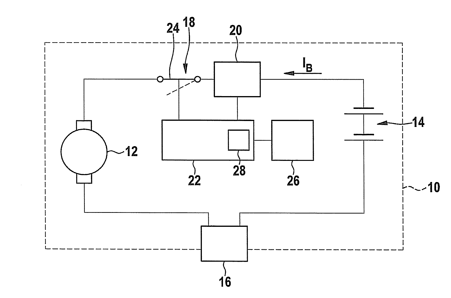
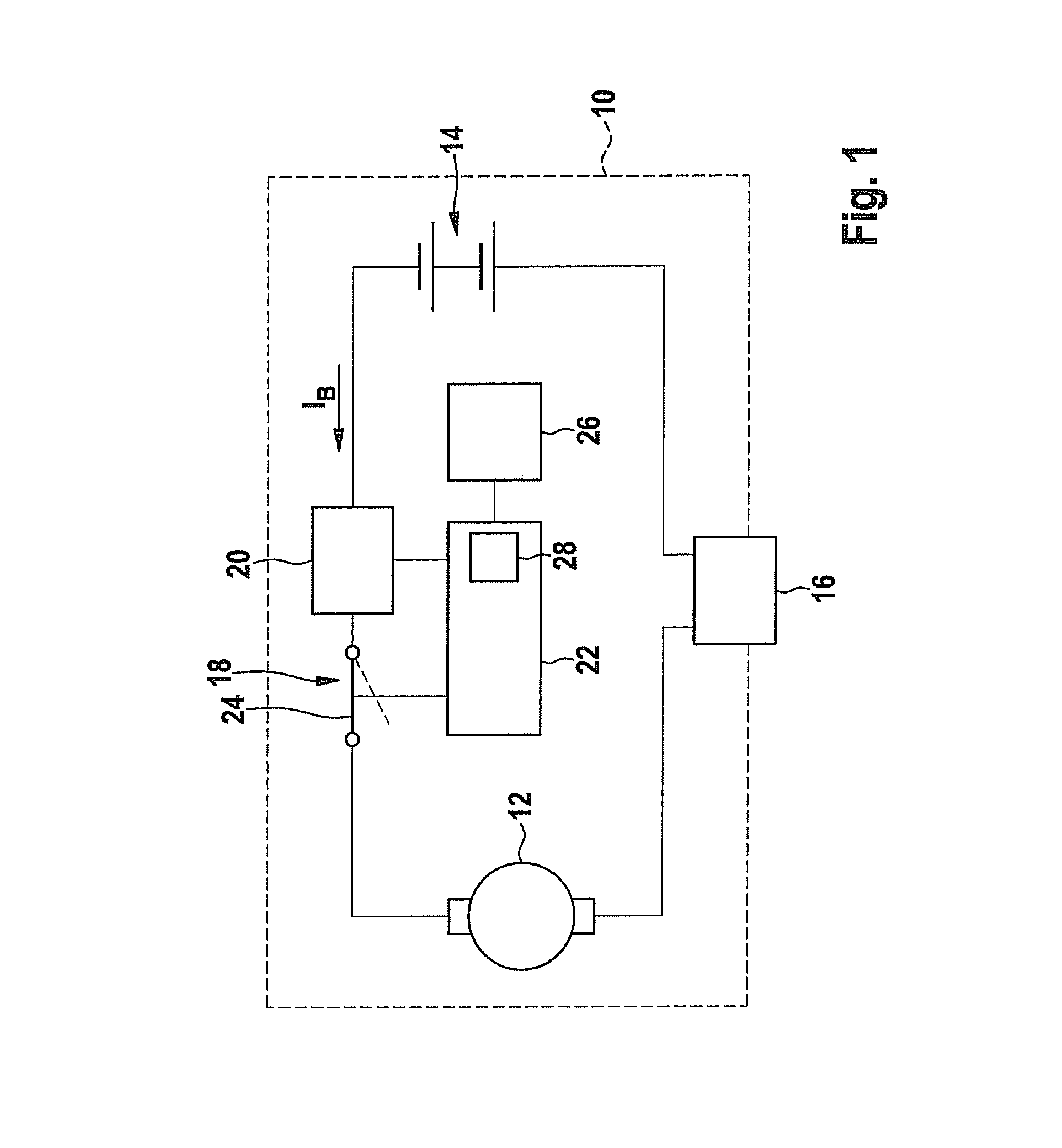
[0024]FIG. 1 shows a hand-held power tool 10 an electric motor 12, hand-held power tool 10 being powered by a storage battery 14. Starting out from storage battery 14, an operating element 16, electric motor 12, an interruption device 18 and a current-measuring device 20 are situated in the electric circuit. Interruption device 18 is controlled by a monitoring apparatus 22. Interruption device 18 has a switch 24 (an implementation in the form of a semiconductor component is also possible), which is normally closed but may be opened, if necessary, by monitoring apparatus 22. The open position of switch 24 is indicated by a dashed line. Finally, storage battery 14 is assigned a temperature-measuring device 26 that measures the temperature of storage battery 14. At least one static, limiting temperature value is stored in monitoring apparatus 22 or in logic device 28; in this case, the static, limiting temperature value being permanently stored in hardware.

[0025]For use of the method a...


PUM


Abstract

In a method for detecting an overload situation in a battery-operated device having an electric motor, a load current of the electric motor is ascertained and used to deduce a thermal overload of the battery in such a manner, that, starting out from a static temperature limit, a temporally variable, maximum permissible temperature limit for the battery is calculated using a specifiable function dependent on the ascertained load current. The calculated, variable temperature limit is compared to a current, measured temperature of the battery, and a thermal overload of the battery is deduced from the result of the comparison.

Description

FIELD OF THE INVENTION[0001]The present invention relates to a method for detecting an overload situation in a battery-operated device having an electric motor, a load current of the electric motor being ascertained and used in order to deduce a thermal overload of the battery. In addition, the present invention relates to a corresponding apparatus.BACKGROUND INFORMATION[0002]An overload monitoring is described in DE 10 2005 038 225.[0003]Numerous types of power tools or electric garden tools may be operated without a connection to a power supply system. For storing the energy in these “cordless” power tools, garden tools or electric vehicles, electrochemical cells are used that are either permanently installed in the device or are situated in batteries removable from the device. In the following, the term “batteries” is used for all such cells, in particular, for rechargeable cells, e.g., Li-ion cells of a storage battery, as well.[0004]In order to ensure the reliability and an ene...

Claims


Application Information

Patent Timeline
Patent Type & Authority Patents(United States)
IPC IPC(8): G01R31/00
CPCH02H5/041H02H7/18H02H3/006
Inventor LIEBENOW, CORNELIUS
Owner ROBERT BOSCH GMBH
Why Eureka
Try Eureka