Releasable tunnel brace for a vehicle

a technology for vehicles and tunnels, applied in the field of vehicle body construction, can solve the problems of occupant injury, noise, vibration or harshness (nvh) increase, and the vehicle can not be rolled back, so as to reduce the nvh, minimize local deflection, and maximum torsion stiffness

Active Publication Date: 2014-06-17
FORD GLOBAL TECH LLC
View PDF2 Cites 5 Cited by
  • Summary
  • Abstract
  • Description
  • Claims
  • Application Information

AI Technical Summary

Benefits of technology

[0012]The disclosed invention provides a releasable tunnel brace that overcomes the limitations of known tunnel brace arrangements by providing a brace that offers robust vehicle torsion stiffness while reducing local deflection in the event of a side impact.
[0017]In its ordinary position the tunnel brace of the disclosed invention provides torsion stiffness for the vehicle and is thus effective at reducing NVH. However, in the event of a side impact, the tunnel brace is pushed vehicle inward and the shoulder of the shoulder bolt fastener passes through the elongated slot and into the round portion where the head of the bolt fastener passes through the substantially rounded portion and thus the channel brace is allowed to be released from its attachment position. Thus the tunnel brace of the disclosed invention provides maximum torsion stiffness while withstanding only a minimum amount of lateral force before it releases and thus minimizes local deflection in the event of a side impact.

Problems solved by technology

While typically being a necessary component in the modern vehicle, the tunnel unfortunately too often plays a role in the increase of one or more of noise, vibration or harshness (NVH) within the vehicle.
While generally providing a satisfactory result in the reduction of vehicle NVH, the inclusion of the tunnel brace introduces another challenge to designers which is a possible negative affect in the event of a side impact.
This local deflection often translates into injury to the occupant.
Particularly, due to the stiffness added by the conventional tunnel brace, the vehicle tunnel does not deform efficiently, thus most the deflection of vehicle occurs at the crash side.
The extra local crush of vehicle structure leads to severe contact between door trim and occupants at the crash side, thus risking occupant safety.
The side impact event imposes severe loading on the structural members of the body.
This situation is complicated by the fact that many compact or mid-sized vehicles have low rocker heights that may pass below the bumper of an impacting vehicle, resulting in high door velocities.
The former class of objects is usually wider than the latter class of objects, and thus the localized damage caused by the pole or pole-like object may create greater localized damage than that caused by the vehicle.

Method used


Image

  • Releasable tunnel brace for a vehicle
  • Releasable tunnel brace for a vehicle
  • Releasable tunnel brace for a vehicle

Examples


Embodiment Construction

[0028]In the accompanying figures, the same reference numerals are used to refer to the same components. In the following description, various operating parameters and components are described for one constructed embodiment. These specific parameters and components are included as examples and are not meant to be limiting.

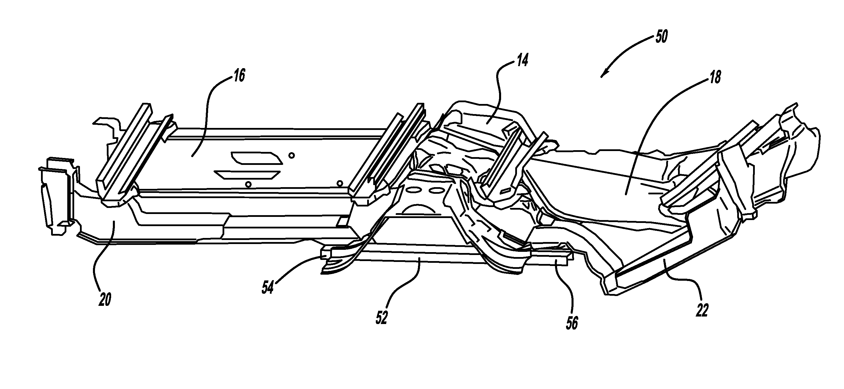
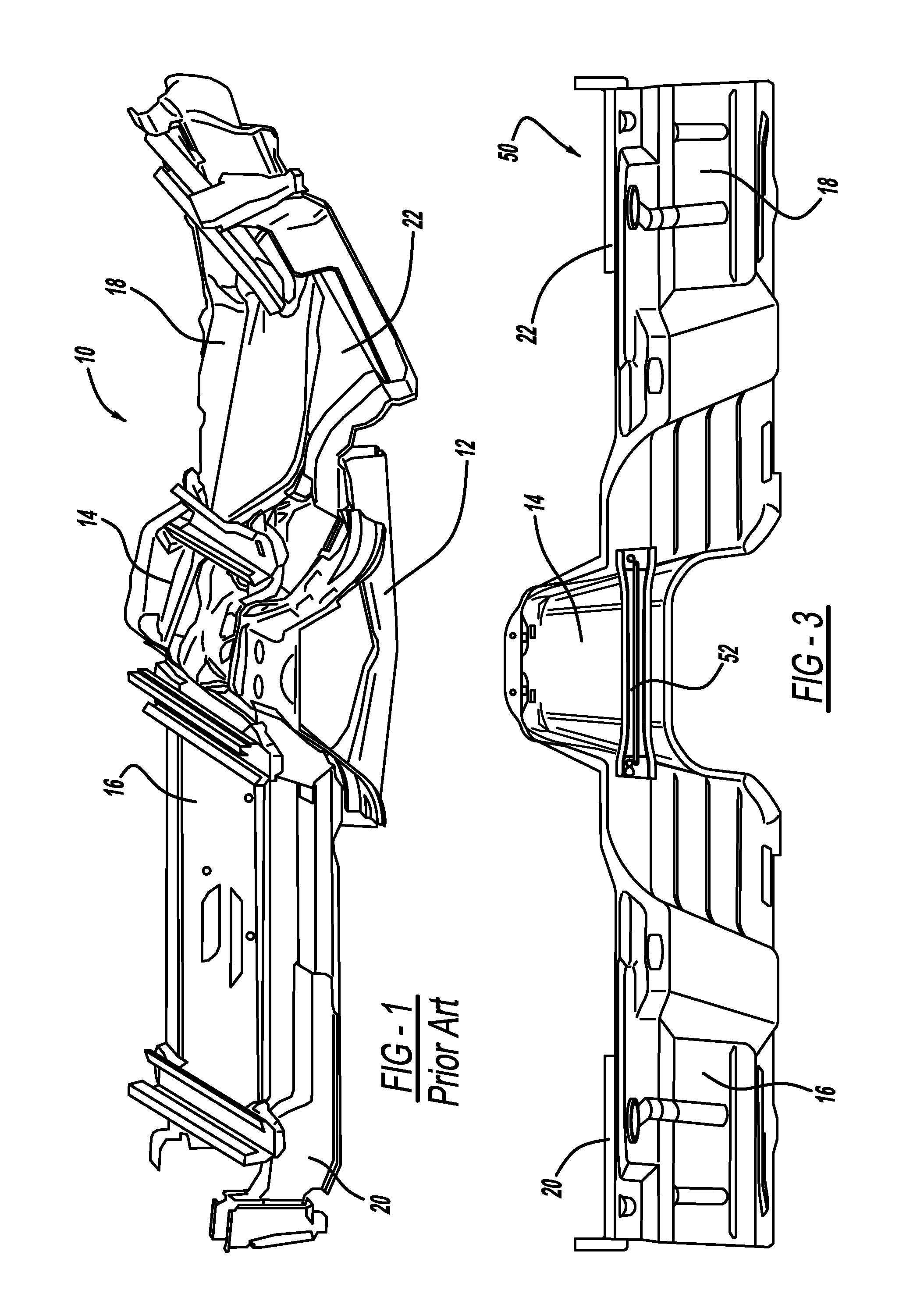
[0029]FIG. 3 illustrates a perspective underside view of the tunnel bridge arrangement according to the disclosed invention, generally illustrated as 50. It is to be understood that the tunnel bridge arrangement 50 as shown is only illustrative and that other variations of the arrangement are possible without deviating from the spirit and scope of the disclosed invention.

[0030]The tunnel bridge arrangement 50 includes a tunnel brace 52 according to the disclosed invention. The tunnel brace 52 extends across the vehicle tunnel 14 between the first floor pan 16 and the second floor pan 18. The tunnel brace 52 is attached at one end to one or the other of the first or...


PUM


Abstract

A releasable tunnel brace for releasably connecting a first side panel to a second panel of a vehicle is disclosed. One or both ends of the brace include a fastener-receiving aperture. The aperture has a round portion and an elongated slot extending therefrom. The round portion can allow the head of a shoulder bolt fastener to pass therethrough. The elongated slot is defined by a pair of opposed walls. The shoulder of the shoulder bolt fastener can pass between the opposed walls. In the event of a side impact, the brace is pushed vehicle inward and the bolt slides through the elongated slot and into the round portion where it is allowed to be released from its attachment position. The brace provides maximum torsion stiffness while withstanding only a minimum amount of lateral force before it releases and thus minimizes local deflection in the event of a side impact.

Description

TECHNICAL FIELD[0001]The disclosed invention relates generally to vehicle body constructions. More particularly, the disclosed invention relates to a tunnel brace that provides required torsion stiffness under normal conditions but is releasable upon side impact to reduce local deflection.BACKGROUND OF THE INVENTION[0002]Most types of vehicle body structures include a centrally-formed tunnel or passage that extends along the long axis of the vehicle generally from the vehicle's firewall rearward to a point behind the second set or row of seats. Various components, such as the transmission, the drive shaft (in the case of the rear wheel drive vehicle), or conduits may extend through the tunnel.[0003]While typically being a necessary component in the modern vehicle, the tunnel unfortunately too often plays a role in the increase of one or more of noise, vibration or harshness (NVH) within the vehicle. To minimize the NVH a tunnel brace is commonly provided between the opposing floor p...

Claims


Application Information

Patent Timeline
Patent Type & Authority Patents(United States)
IPC IPC(8): B62D25/20
CPCB62D25/20
Inventor YANG, HEPING
Owner FORD GLOBAL TECH LLC
Why Eureka
Try Eureka