Injection, sealing valving and passageway system

a sealing valve and passageway technology, applied in the direction of fluid removal, mining structures, borehole/well accessories, etc., can solve the problems of cumbersome screw thread unscrewing, time-consuming operation, and not suited to automation

Inactive Publication Date: 2014-06-17
GRAY PETER ANDREW
View PDF13 Cites 5 Cited by
  • Summary
  • Abstract
  • Description
  • Claims
  • Application Information

AI Technical Summary

Benefits of technology

[0030]The passageways can enable fluids to flow along them without cross contamination with the fluids in another passageway and where at least one of the passageways can accommodate the flow of one or more fluids along them either sequentially or simultaneously. Moreover, the passageways are typically substantially contained within a hollow bar or bolt and are also typically partially contained within an external injector that hydraulically seals with the hollow bar or bolt.
[0035]Preferably the passageways have one or more one-way valve or valves that allow fluids to flow in one direction along the passageways but prevent flow of fluids in the opposite direction along the passageways.
[0038]Preferably as the self drilling rock bolt is inserted into a drilling machine, the valving system which is substantially contained inside the self drilling rock bolt forms a mating and sealing fit with an injection nozzle inside the drilling machine such that a hydraulic seal or hydraulic seals are formed between the passageways in the injection nozzle and the passageways in the bolt. The hydraulically seal or seals can operate when the bolt is being rotated during the drilling cycle, or when the bolt is stationary during the grouting cycle. Water or air or resin or cement grout or other fluids can then be pumped into the self drilling rock bolt through the injection nozzle and into the correct passageway through the valving system without back flow or flow through the wrong passageway thus avoiding premature mixing of fluids or other problems.
[0039]Preferably part of the plastic valving system can substantially wipe the injection nozzle clean when the injection nozzle is withdrawn from the bolt.
[0043]It is particularly preferred that the valving assembly in the bar or bolt can hydraulically seal against a stationary injector even if the valving assembly in the bar or bolt is being rotated.

Problems solved by technology

The screwing and unscrewing of screw threads is a cumbersome operation and where cement grout hoses and fittings are used, it is typically undertaken manually.
This is a time consuming operation and is not suited to automation of the grouting process.
In addition, the use of either screw threads or O Rings for sealing of fluids being pumped through hollow bars is principally designed for sealing against leakage at the seal itself, and they are not designed to direct and control the flow of fluids either inside the drill chuck or inside the hollow bar.
In addition, if an injection nozzle is used in the drilling chuck to inject the two part resin into the hollow bolt, then the two parts of the chemical resin, the mastic component and the catalyst component, must also be kept separate immediately after or above the injection nozzle, otherwise premature curing can occur and cause blockages of this injection nozzle.
Furthermore if the pumping pressures within the mastic component and the catalyst component as they flow out of the injection nozzle are unequal, then it is possible to get backflow of either mastic or catalyst down the wrong passageway, and this can cause blockages within the injection nozzle.
However, the resin injection system as shown in patent number AU199959340 A1 is prone to blockages.
The inventor has found that if the mastic part of a liquid resin and the catalyst part of a liquid resin are allowed to come together immediately at the end of an injector, then the end of the injector is likely to become clogged with resin that has cured and hardened.
Moreover, if two or more fluids are being pumped into a hollow bar simultaneously, the pumping pressures for each fluid may not be equal and this could cause back flow or flow through the wrong passageway.
Furthermore, if separate passageways and one way valves are only used in the injector, clogging of the end of the injector by curing and hardening of two part liquid resins is still possible.
However this patent indicates that this single passageway in the connecting piece has to be flushed out after use, otherwise the two part liquid resins will cure and harden in the passageway entering the bolt making the injector unusable for subsequent bolts.

Method used


Image

  • Injection, sealing valving and passageway system
  • Injection, sealing valving and passageway system
  • Injection, sealing valving and passageway system

Examples


Embodiment Construction

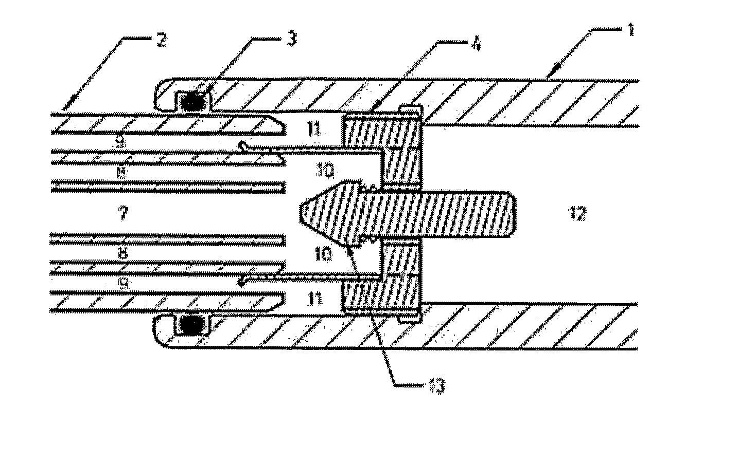
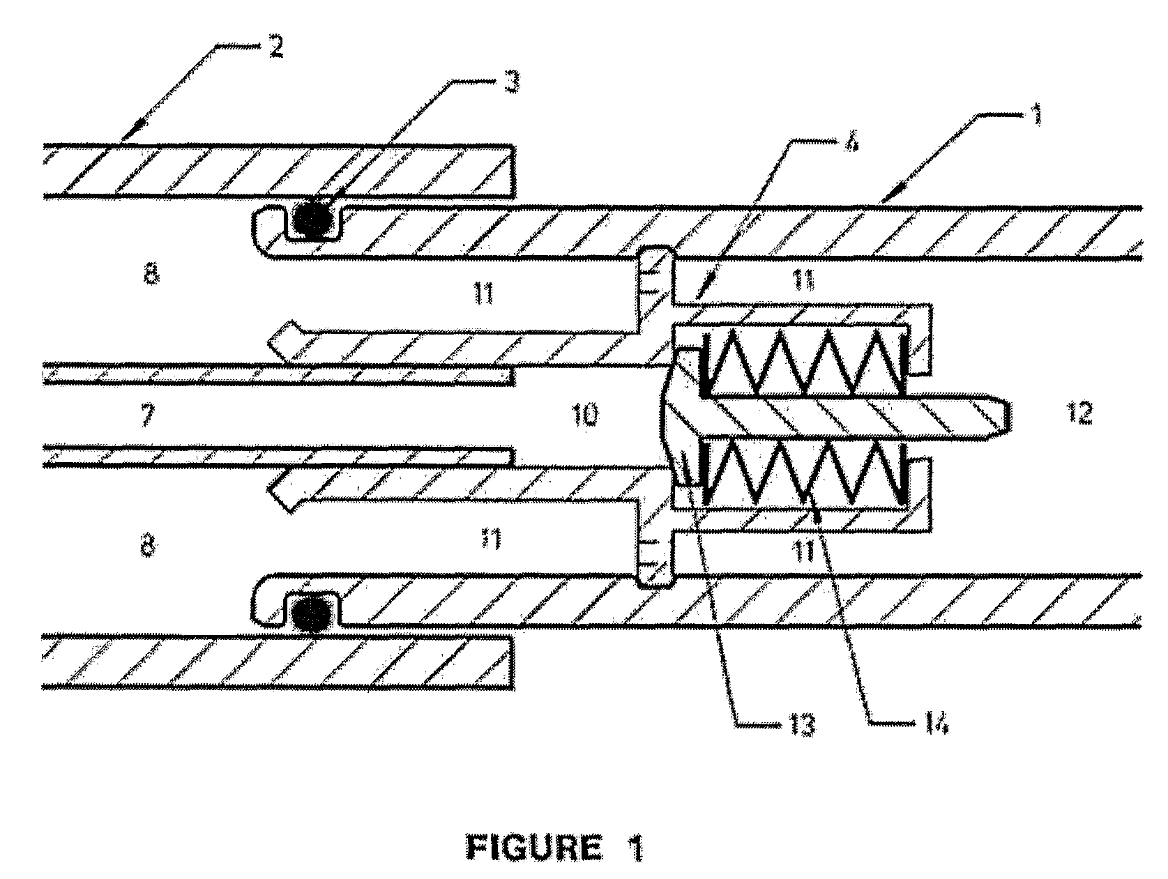
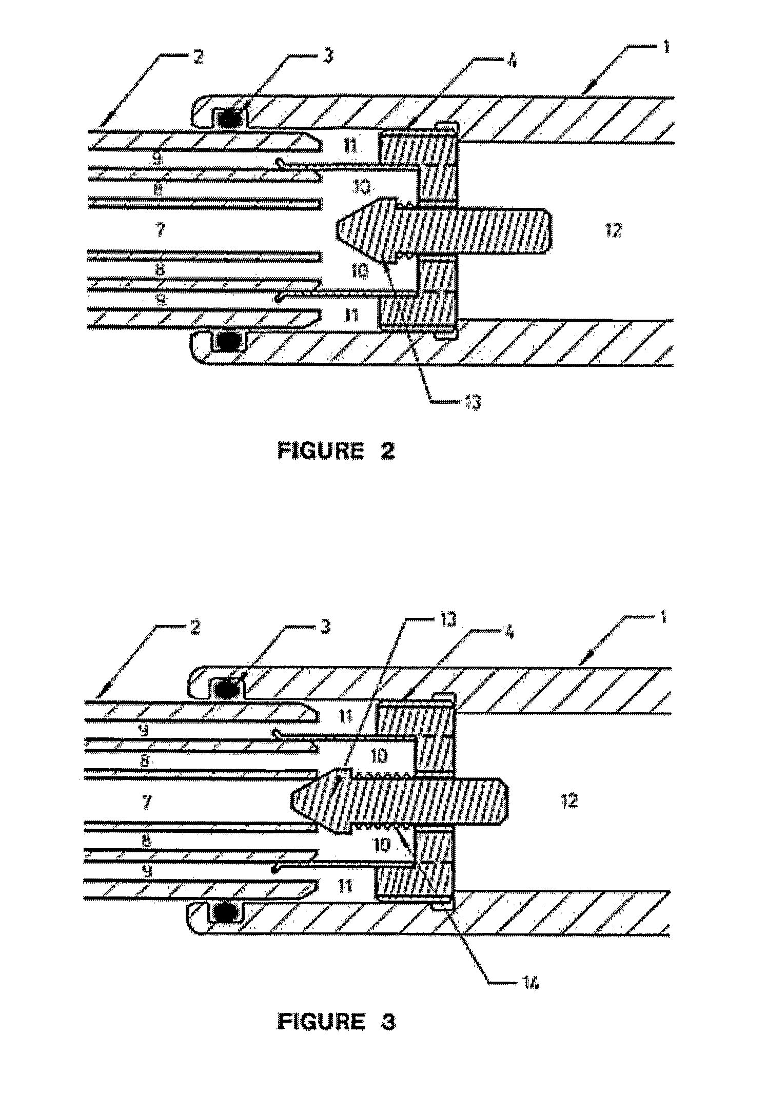
[0066]Where the specification refers to a “bar” or to a “hollow bar” or to a “hollow drill rod” or to a “hollow rock bolt” or to a “hollow self drilling rock bolt” or to a “hollow elongate member” or to a“hollow injection tube” or to a “tube” or to a “pipe” it is to be understood that the invention includes all such variations and modifications of the above including any long hollow elongate member including self drilling rock bolts.

[0067]Where the specification refers to an “injection nozzle” or to a “nozzle” or to “nozzles” or to an “injector” or to an “external injector” it is to be understood that the invention includes all such variations and modifications of one or more injection nozzles that may have one or more passageways which can separate the flow of one or more fluids.

[0068]Where the specification refers to an “injection sleeve” or to a “sleeve” it is to be understood that the invention includes all such variations and modifications of an injection sleeve that can accomm...


PUM


Abstract

The invention provides an injection, sealing, valving and passageway system for use with hollow rock bolts and hollow injection bars used in mining, civil engineering, tunneling and construction including use with hollow self drilling rock bolts. The invention comprises a plurality of passageways with one or more one way flow valves along the passageways. The invention enables one or more fluids to be pumped into a hollow rock bolt or other hollow elongate member either sequentially or simultaneously without cross contamination of fluids in another passageway or back flow of fluids along the wrong passageway. The invention is typically used to install self drilling rock bolts whereby a drilling fluid is initially pumped through the hollow bolt during the drilling cycle, and then a two part chemical resin or cement grout is pumped through the hollow bolt to anchor the bolt in the borehole.

Description

[0001]The invention broadly relates to a valve or valves or passageways, and more specifically, relates to valves and passageways adapted to control the flow of fluids. More specifically still, the invention relates to an injection, sealing, valving and passageway system adapted to direct and control the flow of fluids through hollow drill rods, hollow rock bolts or hollow self drilling rock bolts.BACKGROUND TO THE INVENTION[0002]The flow of fluids, typically water, or air, or cement grout or resin, is commonly pumped through hollow tubes, hollow drill rods, hollow rock bolts and hollow self drilling rock bolts in the mining and tunneling industries. Most commonly water or air is used to flush rock cuttings out of boreholes as they are being drilled by hollow drill rods. Also cement grout or resin is commonly pumped through the central hole in hollow injection rods to stabilise broken, fractured or weak rock or ground. In addition, cement grout or resin is also commonly pumped throu...

Claims


Application Information

Patent Timeline
Patent Type & Authority Patents(United States)
IPC IPC(8): E21D20/02
CPCE21B21/10E21D20/028E21D2021/0053E21D21/0053
Inventor GRAY, PETER, ANDREW
Owner GRAY PETER ANDREW
Why Eureka
Try Eureka