Removing moistening liquid using heating-liquid barrier

a technology of moistening liquid and heating liquid, which is applied in the field of media drying, can solve the problems of reducing effective resolution, reducing image quality, and reducing the strength of the receiving device, and achieves the effects of effective removal of moistening liquid, reducing image damage probability, and increasing thermal power

Inactive Publication Date: 2014-06-24
EASTMAN KODAK CO
View PDF23 Cites 16 Cited by
  • Summary
  • Abstract
  • Description
  • Claims
  • Application Information

AI Technical Summary

Benefits of technology

[0015]An advantage of the present invention is that it effectively removes moistening liquid from a moistened medium. Using a heating liquid can provide a higher thermal power than using a heated gas. Using a liquid-blocking barrier reduces the probability of image damage, and permits using heating liquids that are miscible with the moistening liquid. In various aspects, the heat is applied primarily to the moistening liquid, since concentration-gradient effects draw moistening liquid out of the moistened medium. Various aspects are useful for conventional inkjet printing. Various aspects use reduced quantities of heating liquid, permitting energy savings. Various aspects heat the opposite side of the moistened medium from a printed image, reducing the probability of image degradation.
is that it effectively removes moistening liquid from a moistened medium. Using a heating liquid can provide a higher thermal power than using a heated gas. Using a liquid-blocking barrier reduces the probability of image damage, and permits using heating liquids that are miscible with the moistening liquid. In various aspects, the heat is applied primarily to the moistening liquid, since concentration-gradient effects draw moistening liquid out of the moistened medium. Various aspects are useful for conventional inkjet printing. Various aspects use reduced quantities of heating liquid, permitting energy savings. Various aspects heat the opposite side of the moistened medium from a printed image, reducing the probability of image degradation.

Problems solved by technology

Moreover, the solvent can soak into a receiver, causing the receiver to lose strength or mechanically deform.
The solvent's soaking into a receiver, especially a fibrous receiver such as paper, can also reduce image quality by reducing effective resolution (because the ink spreads) and reducing density (the color of the fibers can show through as the ink soaks in to the receiver).
However, air has a low heat capacity, which limits its ability to transfer heat.
This failure to concentrate the applied heat can slow down the drying process.
Moreover, blowing hot air can smear the ink that is either being jetted or is on the receiver, thereby degrading the image.
Accordingly, it may not be possible to heat the ink without also heating the receiver.
Furthermore, drying different areas of a receiver at different rates can result in wrinkling or distortion of the receiver.
These problems can worsen as the speed of drying increases, or when the receiver is locked in place (e.g., in a nip) while drying.
Moreover, the moisture released during drying can condense on surfaces in a printer.
Drying can also cause paper, especially semi-porous paper, to blister: water within the paper can vaporize, creating sufficient pressure to disrupt the surface of the paper.
However, these schemes use water to remove non-water.
These schemes are therefore unsuitable for inkjet drying.
However, these schemes inherently limit the types of paper that can be used, and coated inkjet papers are generally more expensive than standard commercial papers.
Causing coating material to adhere more effectively to a substrate does not assist with removal of moisture from that substrate.
Sporer teaches that only that portion of the droplet that has not penetrated or feathered into the paper is available for attracting dry ink, so this process is unsuitable for highly-absorbent papers such as newsprint.
Moreover, this process does not remove moisture from the receiver, so drying can still be required.
Also, this process is a hybrid of inkjet and powder printing, so is not suitable for use in conventional inkjet printers.

Method used


Image

  • Removing moistening liquid using heating-liquid barrier
  • Removing moistening liquid using heating-liquid barrier
  • Removing moistening liquid using heating-liquid barrier

Examples


Embodiment Construction

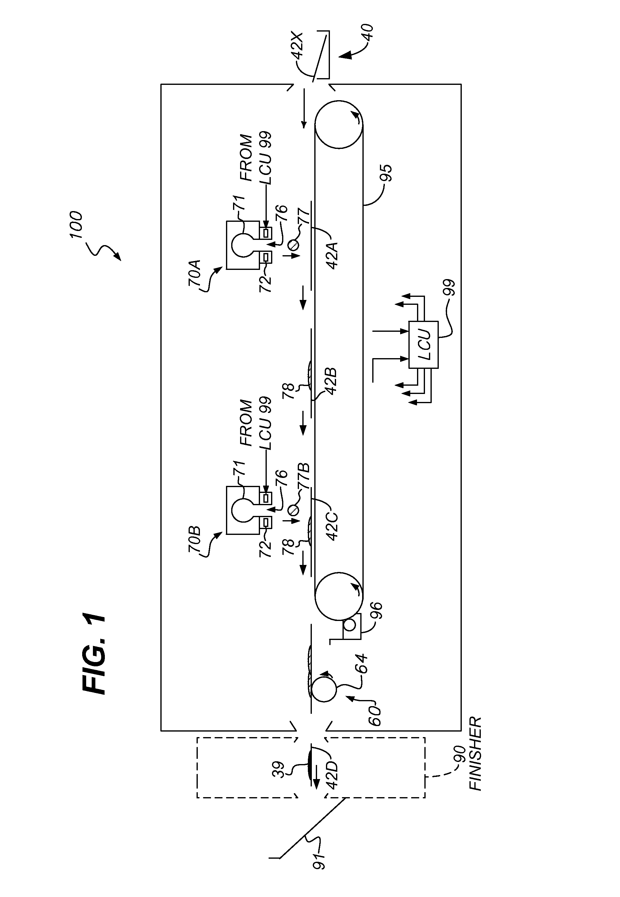
[0026]U.S. Pat. No. 8,251,505 to Hara, entitled “Recording apparatus and method of adjusting temperature of transport belt of recording apparatus,” describes a transport belt that carries a target (e.g., a receiver). The belt is heated to accelerate drying liquid off the target. However, air gaps or bubbles can be present between the receiver and the transport belt. These can be microscopic air bubbles due to the roughness of the receiver or the belt. These bubbles act as insulators, reducing the rate of thermal transfer from the belt to the receiver. Therefore, there is still a need for improved ways of removing moisture from receivers.

[0027]Inkjet printing processes can be embodied in devices including printers, copiers, scanners, and facsimiles, and analog or digital devices, all of which are referred to herein as “printers.” A digital reproduction printing system (“printer”) typically includes a digital front-end processor (DFE), a print engine (also referred to in the art as a ...


PUM


Abstract

A method for removing a moistening liquid from a moistened medium includes providing a liquid-blocking barrier having a first surface and a second surface that is impermeable to a heating liquid. A surface of the moistened medium is brought into contact with the first surface of the liquid-blocking barrier. The heating liquid is brought into contact with the second surface of the liquid-blocking barrier, the heating liquid being at a temperature greater than a moistening-liquid boiling point. Heat is thus transferred through the liquid-blocking barrier from the heating liquid to the moistening liquid, vaporizing the moistening liquid and removing it from the moistened medium.

Description

CROSS-REFERENCE TO RELATED APPLICATIONS[0001]Reference is made to commonly assigned, co-pending U.S. patent application Ser. No. 13 / 649,134, entitled: “Applying heating liquid to remove moistening liquid”, by Priebe et al.; to commonly assigned, co-pending U.S. patent application Ser. No. 13 / 649,139, entitled: “Dryer transporting moistened medium through heating liquid”, by Priebe et al.; to commonly assigned, co-pending U.S. patent application Ser. No. 13 / 649,141, entitled: “Dryer impinging heating liquid onto moistened medium”, by Priebe et al.; to commonly assigned, co-pending U.S. patent application Ser. No. 13 / 649,146, entitled: “Barrier dryer transporting medium through heating liquid”, by Priebe et al.; to commonly assigned, co-pending U.S. patent application Ser. No. 13 / 649,152, entitled: “Dryer with heating liquid in cavity”, by Priebe et al.; to commonly assigned, co-pending U.S. patent application Ser. No. 13 / 649,158, entitled: “Barrier dryer with porous liquid-carrying m...

Claims


Application Information

Patent Timeline
Patent Type & Authority Patents(United States)
IPC IPC(8): F26B11/02
CPCF26B3/22
Inventor PRIEBE, ALAN RICHARDRIMAI, DONALD SAULWHITE, CHRISTOPHER J.SPAULDING, KEVIN EDWARD
Owner EASTMAN KODAK CO
Why Eureka
Try Eureka