Solar panel attachment system

a technology of solar panels and mounting brackets, which is applied in the direction of heat collector mounting/support, solar thermal energy generation, etc., can solve the problems of inability to provide adequate pressure on the seal around the lag screw, the failure of conventional flashing devices to provide adequate pressure, and the inability to separate position the brack

Active Publication Date: 2014-06-24
TESLA INC
View PDF41 Cites 93 Cited by
  • Summary
  • Abstract
  • Description
  • Claims
  • Application Information

AI Technical Summary

Problems solved by technology

Prior art attempts to develop such flashing devices have suffered from a number of drawbacks.
For example, some conventional flashing devices do not provide adequate pressure on the seal around the lag screw.
Others do not allow for a separately positionable bracket that enables adjustability relative to the lag screw after installation thereof.
Others do not work well with rail-free mounting systems such as those disclosed in prior art patents and other patents and applications of common assignee and at least one common inventor.
And still others are costly, do not optimize materials usage, create seals from brittle materials that have higher failure rates than resilient materials, require expensive manufacturing methods, and / or do not properly account for misalignment of components during installation.
Other limitations of the related art will become apparent to those of skill in the art upon a reading of the specification and a study of the figures.

Method used


Image

  • Solar panel attachment system
  • Solar panel attachment system
  • Solar panel attachment system

Examples


Embodiment Construction

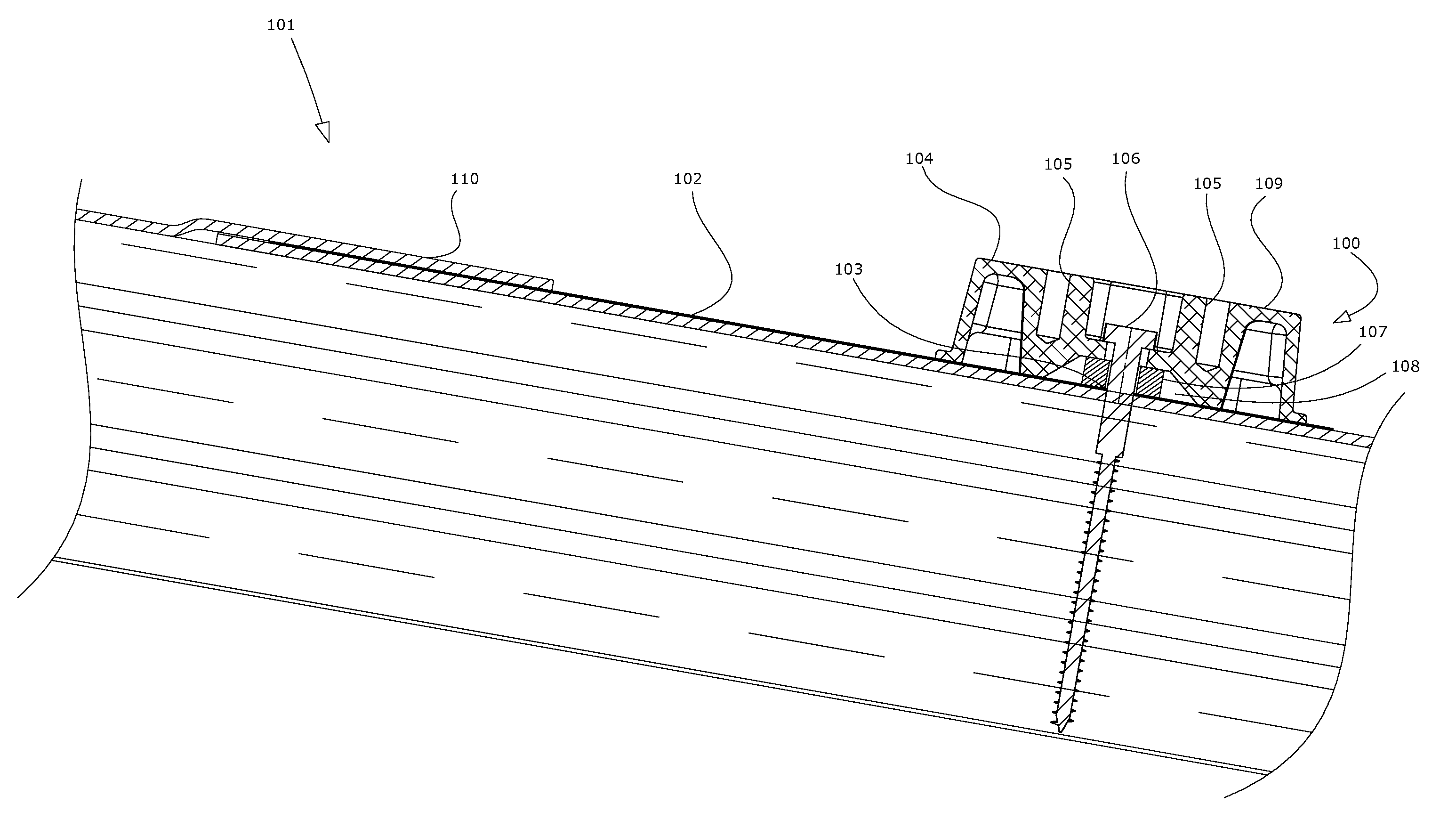
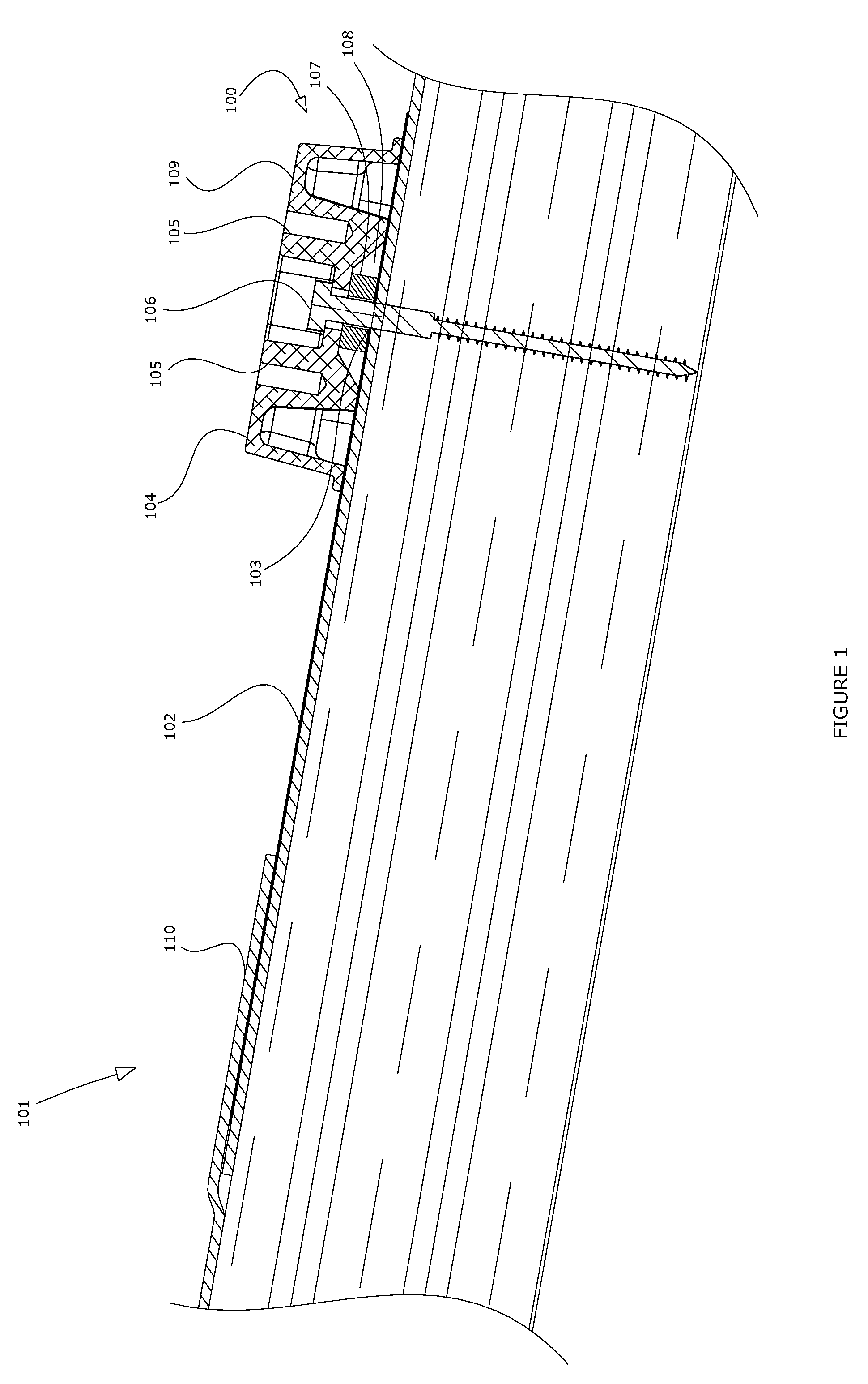
[0048]Referring to FIG. 1, and more generally in the other figures wherein the same reference numerals refer to like components in the various views, there is illustrated a new and improved attachment system for solar equipment, such as but not limited to photovoltaic and solar thermal panels or modules and ancillary apparatus, generally denominated 100 herein. Other solar equipment may include, but not be limited by, thermal solar arrays, electrical equipment, ancillary supporting and connecting apparatus (such as one or more inverters, wires, conduits, interlocks, feet, snow dams, wind diffusers, cosmetic screens, measurement equipment, and other devices as are known in the art). While various terms may have their ordinary meaning or particular meaning in the art, for ease of understanding there is provided herein, both below and at other locations in this specification, a non-limiting explanation as to the minimum scope intended for understanding of the present specification. Ter...


PUM


Abstract

A method, system and apparatus are disclosed regarding an attachment system for solar equipment, sometimes referred to as a flashing device allowing quick and easy assembling of the solar equipment into an array or other combination in a sturdy and durable manner. In examples of the present technology, a flashing device may include a flashing plate which may contain one or more raised features to further direct and control the flow of liquid over the flashing plate. The flashing device may also contain a fluid restrictor such as a seal or part of a seal usually held within an aperture of a block having a skyward facing essentially or substantially flat surface. One or more various items of solar equipment may be attached to the essentially flat surface of the block. Also disclosed are adjustable mounting feet which may be installed in connection with other solar equipment.

Description

CROSS REFERENCES[0001]This application claims the benefit of the filing date of U.S. Provisional Patent Application Ser. Nos. 61 / 557,821, filed Nov. 9, 2011, entitled “Photovoltaic Module Mounting Foot Base with Integral Spring,” and 61 / 656,230, filed Jun. 6, 2012, entitled “Flashing Apparatus, System and Method.” The foregoing applications are incorporated by reference in their entirety as if fully set forth herein.BACKGROUND[0002]Solar panels and related equipment are frequently mounted on support structures (such as roofs), or other objects that require a substantially water-tight or water-resistant connection. For example, solar panels mounted on a roof of a building are commonly attached to the roof via an attachment system that includes one or more flashing devices that allow a roof-penetrating member, such as a lag screw, to penetrate a portion of a roofing membrane without compromising the roof's ability to prevent water from entering the building.[0003]Prior art attempts to...

Claims


Application Information

Patent Timeline
Patent Type & Authority Patents(United States)
IPC IPC(8): E04H14/00E04D13/18
CPCH01L31/0482E04B1/68F24J2/5245Y02B10/12Y02B10/20H01L31/0422Y02E10/50F24J2002/5296F24J2/5258E04B1/38F24J2/5205F24J2/5228F24J2/5249F24J2/5252F24J2/5254F24J2/5266F24J2002/5226F24J2002/5294H01L31/042H01L31/0481H02S20/23Y02E10/47F24S25/33F24S25/61F24S25/636F24S2025/021F24S2025/022F24S2025/807Y02B10/10F24S25/40F24S25/615F24S25/63F24S25/632
Inventor WEST, JOHN R.HUDSON, TYRUSMOLINA, DAVIDCAPSUTO, IAN
Owner TESLA INC
Why Eureka
Try Eureka