Vibration wave driving apparatus

a driving apparatus and vibration wave technology, applied in the direction of piezoelectric/electrostrictive/magnetostrictive devices, piezoelectric/electrostriction/magnetostriction machines, electrical apparatus, etc., can solve the problems of difficult to provide the frictional surfaces of the ultrasonic vibrator b>3/b> and the driven body b>4, and achieve the effect of stable contact state and increase in the number of components

Inactive Publication Date: 2014-06-24
CANON KK
View PDF9 Cites 7 Cited by
  • Summary
  • Abstract
  • Description
  • Claims
  • Application Information

AI Technical Summary

Benefits of technology

[0041]With the use of elastic deformation of the elastically-deformable portion 13e, a support effect for the ultrasonic vibrator 3 in the ultrasonic vibrator unit 2 is obtained.
[0061]In view of the above problems, an object of the present invention is to provide a vibration wave driving apparatus which can restrain increases in the number of components and in necessary space and which can maintain a stable contact state of frictional surfaces of a vibrator and a driven body.
[0063]According to the present invention, a vibration wave driving apparatus which can restrain increases in the number of components and in necessary space and which can maintain a stable contact state of frictional surfaces of a vibrator and a driven body can be realized.

Problems solved by technology

However, in a practical sense, it is extremely difficult to provide the frictional surfaces of the ultrasonic vibrator 3 and the driven body 4 at parallel positions due to manufacturing errors of components, installation errors, and the like.

Method used


Image

  • Vibration wave driving apparatus
  • Vibration wave driving apparatus
  • Vibration wave driving apparatus

Examples


embodiment 1

[0098

[0099]As Embodiment 1 is described an exemplary configuration of a vibration wave driving apparatus to which the present invention is applied.

[0100]The vibration wave driving apparatus of the present embodiment includes a vibrator including a vibration body having a frictional surface and an electrical-mechanical energy conversion element, and a driven body which has a frictional surface having contact with the frictional surface of the vibrator and which is configured to be pressed through the respective frictional surfaces.

[0101]Further, the vibration wave driving apparatus is configured so that the driven body is relatively moved by elliptic motion of the vibrator through those respective frictional surfaces.

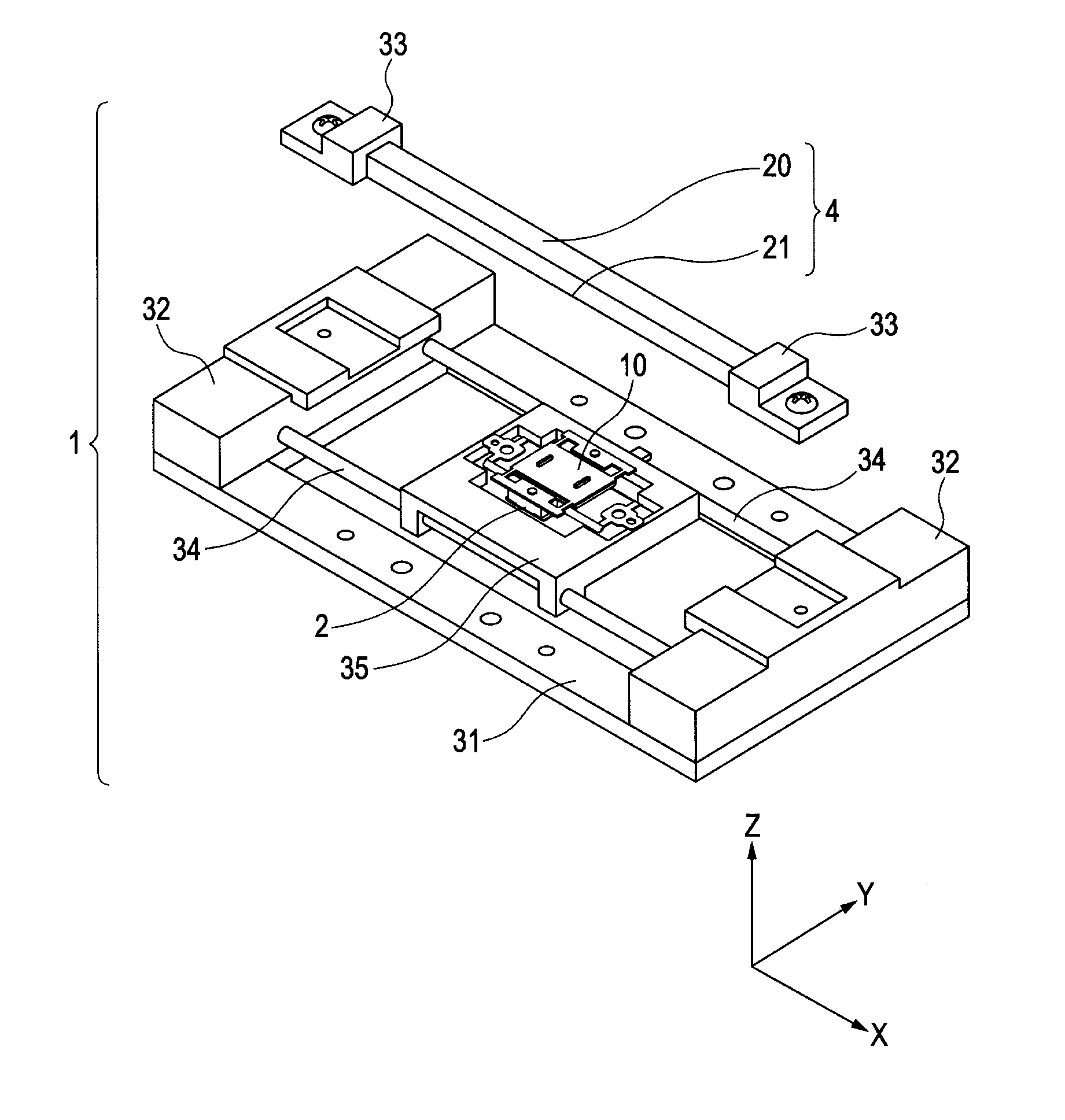
[0102]More specifically, as shown in FIG. 1, a vibration wave driving apparatus 1 of the present embodiment is configured as an apparatus which includes what is called an ultrasonic motor as a source of a driving force and which performs linear driving with one degree of...

embodiment 2

[0163

[0164]As Embodiment 2, the following describes an exemplary configuration of a vibration wave driving apparatus having a different configuration from that in Embodiment 1, with the use of FIGS. 8A and 8B.

[0165]FIG. 8A shows a perspective view of a supporting member 13 in the present embodiment.

[0166]A vibration wave driving apparatus 1 in the present embodiment has the same configuration as in Embodiment 1 except the supporting member 13, and therefore the explanation that has been already given is omitted.

[0167]Even the supporting member 13 is the same as that explained in FIGS. 4A to 4C except some parts, and therefore the explanation that has been already given is omitted.

[0168]FIG. 8B shows a YZ cross-section of elastically-deformable portions 13c taken along the position shown with reference signs S in FIG. 8A.

[0169]A reference sign C1 in the figure is the intersection (a rotation center of rotational deformation) of the extended lines of the cross-sections of the elastica...


PUM


Abstract

A vibration wave driving apparatus includes a vibrator for driving a driven body and a member for supporting the vibrator. The construction can restrain increases in the number of components and in necessary space and can maintain a stable contact state of frictional surfaces of the vibrator and the driven body.

Description

BACKGROUND OF THE INVENTION[0001]1. Field of the Invention[0002]The present invention relates to a vibration wave driving apparatus. Particularly, the present invention relates to a vibration wave driving apparatus for relatively moving an ultrasonic vibrator and a driven body by combining vibrations of different vibration modes.[0003]2. Description of the Related Art[0004]A vibration wave driving apparatus for relatively moving an ultrasonic vibrator and a driven body by combining vibrations of different vibration modes has been proposed.[0005]Such a vibration wave driving apparatus has a pressure-application structure to generate a frictional force between the ultrasonic vibrator and the driven body.[0006]Further, the vibration wave driving apparatus is given a support structure for maintaining abutment of frictional surfaces formed between the ultrasonic vibrator and the driven body with an appropriate relation.[0007]As this support structure, some methods have been proposed.[000...

Claims


Application Information

Patent Timeline
Patent Type & Authority Patents(United States)
IPC IPC(8): H02N2/04
CPCH02N2/026H02N2/0025H02N2/0015
Inventor KOJIMA, NOBUYUKI
Owner CANON KK
Why Eureka
Try Eureka