Concrete deck measuring device

a measuring device and concrete technology, applied in the direction of mechanical measuring arrangement, instruments, machines/engines, etc., can solve the problems of increasing the cost of repair, restoration, or complete reconstruction, giving the inspector the false impression that the deck is not thick enough in that particular location, and hasty and inaccurate depth measurement, etc., to achieve easy-to-read measurement

Active Publication Date: 2014-07-01
SPEAR IV H HOUSTON
View PDF16 Cites 13 Cited by
  • Summary
  • Abstract
  • Description
  • Claims
  • Application Information

AI Technical Summary

Benefits of technology

[0022]It is yet another object of the present invention to provide a multi-purpose device for measuring the depth of a plastic concrete bed utilizing a depth probe having a indicator configured to translate over a measured scale to provide an easy to read measurement.
[0023]It is yet another object of the present invention to provide a multi-purpose depth measuring device that is self-contained such that the user need not carry or implement any additional tools or measuring devices around the work site.
[0024]It is yet another object of the present invention to provide a multi-purpose depth measuring device that is durable and capable of being provided in a variety of concrete and other plastic aggregate materials regardless of the size, shape, and volume of solid aggregate material.

Problems solved by technology

As is well known in the art, the process of pouring, consolidating, and finishing the concrete is a very fast paced operation usually occurring at night under severe time constraints dictated by the necessity for ingress / egress over the particular structure being built, repaired, or refinished.
Despite the rapid pace and stringent time constraints, concrete bridge decks are expected to be constructed in accordance with a set plan or blueprint and deviation from the plan can lead to increased costs due to repair, restoration, or complete reconstruction.
There are a few problems and disadvantages that are apparent when the stiff wire or dowel rod method of inspection is used.
While a dowel rod might be somewhat larger and less prone to deflection or deformity, the bottom end can often times hit a coarse aggregate squarely, giving the inspector the false impression that the deck is not thick enough in that particular location.
In addition to the problems encountered while measuring the total thickness of the deck, the inspector must also measure the depth of the concrete cover over the rebar.
The time constraints and cumbersome nature of employing two tools and a tape measure eventually leads to hasty and inaccurate depth measurement.
Several attempts at providing such an improved tool have been made, however none have sufficiently solved the problems outlined above.
Accordingly, while providing a general depth gauge, the device in Baker fails to provide a means to measure a concrete cover layer which may be disposed above a grid of rebar or other support structure having interstitial spacing.
Additionally, the foot of the device in Baker will not provide a stable base for measuring depths of concrete below the rebar grid.
Sarlandt does not provide a measure to measure a depth of concrete below a supporting rebar grid nor does it provide a blade for measuring the cover above the rebar.

Method used


Image

  • Concrete deck measuring device
  • Concrete deck measuring device
  • Concrete deck measuring device

Examples


Embodiment Construction

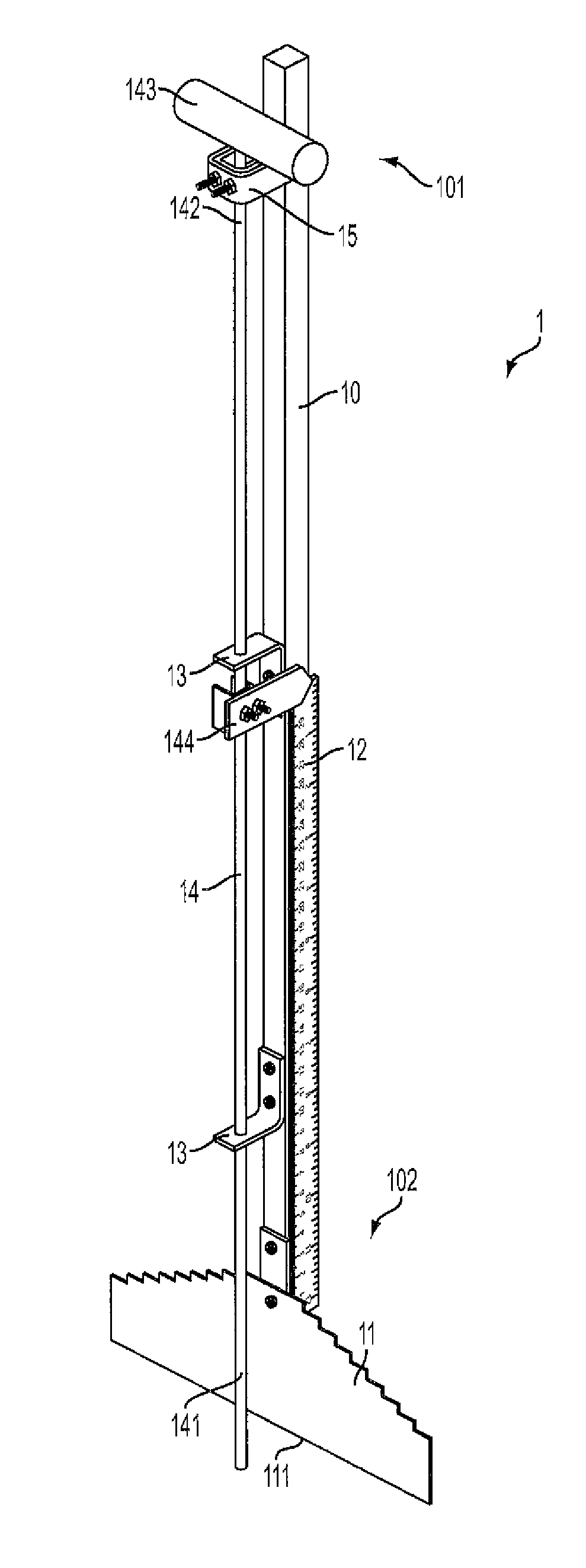
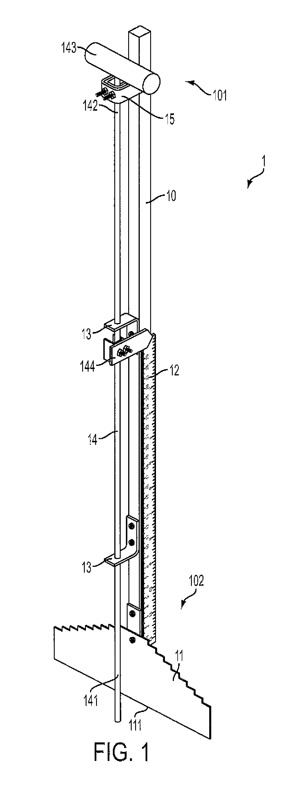
[0031]FIG. 1 is a perspective view of one embodiment of the present invention. Shown is measuring device 1 comprising a primary support spine 10 having a proximal end 101 and a distal end 102. Support spine 10 comprises an elongated substantially rigid member configured as a rod or similar structure. Spine 10 may have any suitable cross-section sufficient to provide rigid support. For example, spine 10 may have a circular, square, or rectangular cross section. In some embodiments, spine 10 comprises a length of square bar composed of steel, aluminum, another like metal, or other suitable lightweight rigid material. Other materials and configurations of spine 10 are contemplated, provided spine 10 is suitably rigid to support its attendant components and to carry out the intended functions disclosed herein.

[0032]Fixed to the distal end 102 of spine 10 is a stepped blade 11 which, in some embodiments, is transversely disposed with respect to the length of spine 10. Stepped blade 11 fu...


PUM


Abstract

A device for measuring the depth of concrete comprising an elongated spine, a stepped blade attached at the distal end of the spine and having a plurality of bi-lateral steps having a predetermined width and height tapering toward the distal end of the spine, a depth probe slidably attached longitudinally along the spine and including an indicator; and a scale aligned with the indicator. The depth probe may have a pointed or beveled distal tip which is useful for penetrating concrete or other aggregate materials. The stepped blade is provided into concrete and comes in contact with the top of the rebar grid, with the steps measuring the depth of the concrete cover over the rebar. The depth probe is plunged into the concrete until the tip reaches the bottom. The scale measures the distance between a distal tip of the depth probe and the leading edge of the blade.

Description

CROSS REFERENCE TO RELATED APPLICATIONS[0001]N / ASTATEMENT REGARDING FEDERALLY SPONSORED RESEARCH OR DEVELOPMENT[0002]N / ABACKGROUND OF THE INVENTION[0003]1. Field of the Invention[0004]The present invention generally relates to depth gauges and measuring devices and more particularly to a device for measuring the depth of concrete decks, roads, streets, highways, and related structures.[0005]2. Description of Related Art[0006]Most modern bridges and similar structures are constructed by pouring a concrete deck over a matrix of beams. Once the beams matrix is placed, forms or molds are connected to the beams to provide support for the plastic concrete as it is poured and finished in accordance with a predetermined construction plan or blueprint. Typically, two layers or grids of tied rebar are placed on top of the beams before the concrete is poured. The rebar provides internal structural support for the eventual concrete slabs that will be formed. As is well known in the art, the pro...

Claims


Application Information

Patent Timeline
Patent Type & Authority Patents(United States)
IPC IPC(8): G01B5/18G01F23/04G01B5/06
CPCG01F23/04G01B3/28G01B5/066
Inventor SPEAR, IV, H., HOUSTON
Owner SPEAR IV H HOUSTON
Why Eureka
Try Eureka