
Synergistic welding and electrode selection and identification method

a welding electrode and synergistic technology, applied in the direction of non-electric welding apparatus, rigid containers, packaging, etc., can solve the problems of affecting the identification of welding electrode properties and characteristics, and affecting the identification of welding electrodes

Active Publication Date: 2014-07-01
LINCOLN GLOBAL INC
View PDF14 Cites 23 Cited by
  • Summary
  • Abstract
  • Description
  • Claims
  • Application Information

AI Technical Summary

Benefits of technology

[0060]By employing various embodiments of the present invention, the efficiency of welding and inventory management can be increased, as well as increasing the quality of welding by avoiding errors in setting appropriate welding output parameters.

Problems solved by technology

However, because some of these differences, such as chemical composition, are not easily discernable by the naked eye or even upon close examination it can be difficult for a welder to properly distinguish between welding electrodes.
However, identification of the properties and characteristics of the electrode merely from the packaging can also be difficult.
Additionally, the identification information packaging (such as spools or boxes) can be compromised or otherwise rendered illegible because of the environments in which welding takes place.
Thus, even when the electrode packaging contains electrode information, easy identification of the electrode can be difficult.
Additionally, once an electrode is removed from its packaging it can be very difficult to determine the properties of the electrode.
Because of the nature of these controls and the potential for misidentifying the characteristics of the electrode, there is a possibility that a welder would input the wrong settings, resulting in an improper weld.
Additionally, because of the limitations on current electrode packaging, as discussed above, it is difficult to easily inventory or otherwise identify welding electrodes.

Method used


Image

  • Synergistic welding and electrode selection and identification method
  • Synergistic welding and electrode selection and identification method
  • Synergistic welding and electrode selection and identification method

Examples


Embodiment Construction

[0015]Exemplary embodiments of the invention will now be described below by reference to the attached Figures. The described exemplary embodiments are intended to assist the understanding of the invention, and are not intended to limit the scope of the invention in any way. Like reference numerals refer to like elements throughout.

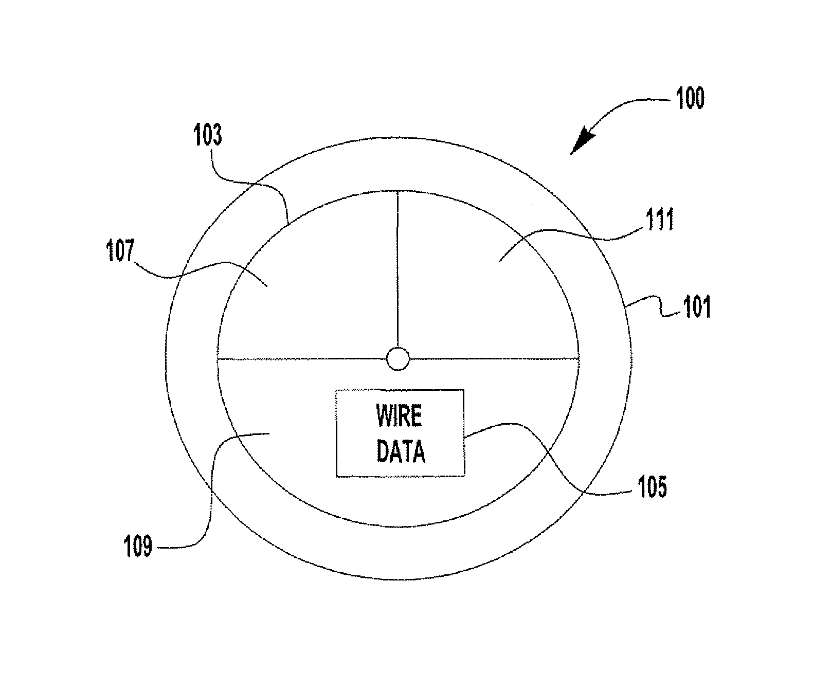
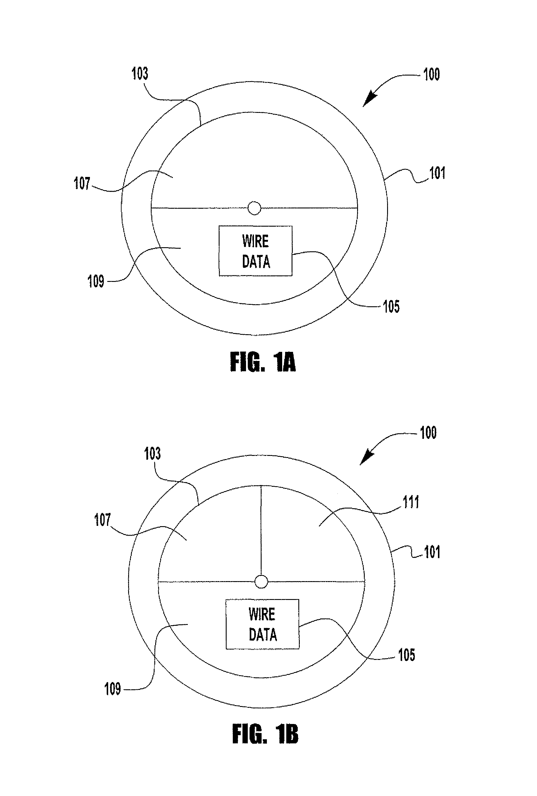
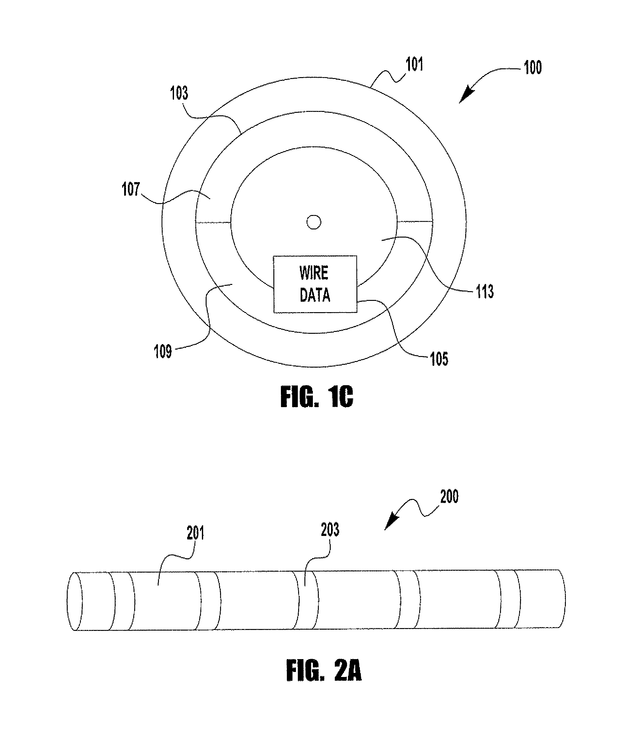
[0016]FIGS. 1A through 1C diagrammatically illustrate a spool 100 in accordance with various exemplary embodiments of the present invention. A welding electrode (not shown) is wound on the spool 100 so that as the electrode is consumed it can be drawn from the spool. For example, in a semi-automatic MIG welding process often a wire feeding device (not shown) is employed, where the spool 100 is mounted onto the wire feeding device. Thus, the electrode can be continuously fed to the weld as needed during the welding operation. The spool 100 is of any known construction, size, etc. In fact, any known or used spools 100 can be used. The present invention is no...


PUM

PropertyMeasurementUnit
coloraaaaaaaaaa
shapeaaaaaaaaaa
physical dimensionaaaaaaaaaa

Abstract

A method of identifying and selecting welding electrodes and welding output parameters on a welding power source is provided. The method includes identifying electrodes and / or electrode packaging with distinct colors and / or patterns which correspond to properties of the electrode. The method also may include employing distinguishable identifying markings on a power supply which correspond to the electrodes to be used to allow for easy setting of output parameters.

Description

BACKGROUND OF THE INVENTION[0001]1. Field of the Invention[0002]Devices, systems, and methods consistent with the invention relate to a method and apparatus of selecting welding parameters and electrodes.[0003]2. Description of the Related Art[0004]Welding requires the use of welding electrodes. Because of the wide variations and differences in each welding application, welding electrodes have widely varying characteristics. For example, welding electrodes have varying diameters and chemical compositions. Additionally, some electrodes are self-shielding (e.g., FCAW), while others are solid metal electrodes. With these widely varying characteristics, the use of the proper electrode for a particular welding operation is important to ensuring that a satisfactory weld is achieved. However, because some of these differences, such as chemical composition, are not easily discernable by the naked eye or even upon close examination it can be difficult for a welder to properly distinguish bet...

Claims


Application Information

Patent Timeline
Patent Type & Authority Patents(United States)
IPC IPC(8): B23K11/04B65D85/02B23K13/08
CPCB23K9/1056B23K9/125B23K9/133
Inventor BLANKENSHIP, GEORGEMICCO, ROBPAPINEAU, ARTHUR B
Owner LINCOLN GLOBAL INC
Learn More